Special Focus: Hydrogen Infrastructure Development
Realize energy and environmental benefits with circular H2 from waste gasification
G. Rispoli, A. Salladini and A. Borgogna, MyRechemical, Rome, Italy; and G. Iaquaniello, NextChem, Rome, Italy
Increasing concerns about environmental pollution related to greenhouse gas (GHG) emissions is promoting the energy transition toward more sustainable energy production systems. These systems are based on renewable energy exploitation and circular economy principles.
The concept of sustainability is often coupled to the concept of waste valorization as a driver for rethinking conventional production systems. Such vision, aiming for a more sustainable use of resources, is also supported by the European Commission through a policy stating that “…waste management should be improved and transformed into sustainable material management with a view to promoting the principles of the circular economy, enhancing the use of renewable energy and providing new economic opportunities.”1
The concept of circular economy is redesigning many industrial fields with the aim of waste stream valorization. In the field of solid waste, municipal and plastic waste management is receiving urgent attention from many governments. As a consequence of the Chinese government’s January 2018 ban on the import of waste from foreign countries, many industries in developed countries began to face challenges due to limited installed waste management capacity.2
At present, approximately 2 billion metric tons per year (metric Btpy) of waste are globally produced. By 2050, this volume is anticipated to reach 3.4 metric Btpy due to expected increases in population and GDP, which both influence yearly waste production value.3 This scenario may worsen as increases in living standards will inevitably bring higher consumption and higher waste production.
Both chemical production and waste disposal by incineration imply high GHG emissions. However, combining waste recovery and production of chemicals into one process brings the benefits of synergy and allows for significant reductions in overall emissions. The conversion of waste into a chemical also simultaneously solves the issue of waste disposal and the substitution of fossil feedstock. In this way, waste is valorized as a source of carbon and hydrogen, representing a widely available renewable source without geographical restrictions.
The “waste-to-chemicals” approach is also favored from an economic point of view, as the waste feedstock becomes a source of revenue, rather than a cost. The waste fractions that are taken into account as sources in the waste-to-chemicals process are indeed fractions that alternatively would have been disposed through, at worst, landfilling or, at best, incineration with energy recovery. The waste-to-chemicals process allows carbon and hydrogen recovery—i.e., material and energy recovery.
Refuse-derived fuel (RDF), the dry fraction of unsorted municipal solid waste (MSW) and a fraction of unrecycled, sorted plastic waste (PW) are the types of waste eligible for the waste-to-chemicals process. In this article, an innovative route for circular H2 production is presented and described from technical, economic and environmental points of view.
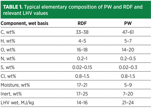
Typical compositions for MSW, RFD and PW feedstocks are reported in Table 1. As shown by the elementary composition, carbon content may vary from 30 wt%–60 wt%, while H2 is in the range of 4 wt%–7 wt%. If properly converted into syngas, then waste may be used for the synthesis of a wide range of chemicals.4
Under this scenario, technology plays a major role in the full implementation of a circular economy around the concept of waste as feedstock for industrial processes. This paradigm implies a robust and reliable technology able to manage the heterogeneous nature of waste, as well as their pollutants content.
The proposed technology allowing the conversion of waste into chemicals is based on a high-temperature gasification process carried out in a pure oxygen (O2) environment. A schematic view of a gasifier reactor, in which such conversions are performed, is shown in Fig. 1.
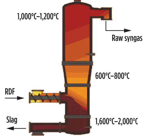
Fig. 1. High-temperature gasification reactor.
The gasifier reactor consists of three sections:
Multiple injections of O2 and auxiliary fuel along the reactor help maintain temperature at 1,600°C–2,000°C in the melting zone, at 600°C–800°C in the gasification zone and up to 1,100°C–1,200°C at the top. Such a temperature profile ensures the full conversion of waste into two products: a highly valuable syngas that is rich in H2 and CO and is free of char, tar, dioxin and furans discharged from the top of the reactor; and an inert vitrified material discharged on the bottom.5 The high temperature in the melting zone allows for discharge of the inert components of waste (minerals and metals) in a granulated and vitrified state, ideally carbon-free. Depending on local legislation, such material can be valorized into the cement or construction industry, or otherwise disposed as standard waste.
As reported by Salladini et al.,6 the syngas yield and relevant composition are mainly affected by the lower heating value (LHV) and the carbon-to-oxygen (C/O) ratio. In general, higher LHV results in higher syngas yield, higher CO and H2 content and lower concentration of CO2. Produced syngas contains, as the major components, CO, H2, CO2, as well as minor quantities of volatile metals and other particles. Fig. 2 shows a block diagram of the gasification section, together with the preliminary cleaning and syngas purification section.
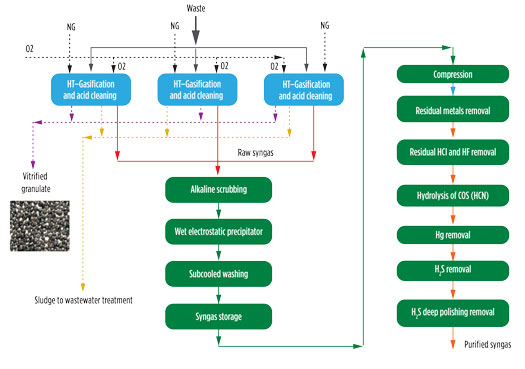
Fig. 2. Block scheme for gasification and syngas preliminary cleaning and purification.
As a first step, the hot gas exiting the reactor is routed to an evaporative quench, where temperature is abruptly reduced to 85°C–90°C by direct injection of water. Although a loss of high-temperature heat is observed, this rapid cooling freezes the chemical composition achieved at high temperature, thereby avoiding undesired reactions. The two-phase mixture at the bottom exit of the quench is routed to a sedimentation tank. This unit allows for collection of the bottom sludge, which is continuously removed from the system, and clarified water is reused as cooling water in the quench. The sedimentation works under a low-pH condition (1.5–3) to promote the migration of volatile metals in the liquid phase. The syngas exiting the sedimentation tank is routed to an acidic column that further promotes metals removal.
Syngas exiting from the acidic columns of each gasification line is collected and sent to a common section based on an alkaline scrubbing column, wet electrostatic precipitators (WESP) and a subcooling column. The water stream collected from the bottom of the washing columns are routed to the wastewater treatment unit, due to the potential presence of pollutants.
The gasifier works under atmospheric pressure and achieves pressure on the order of a few mbar at the end of the cleaning section. In this scheme, a compression section is needed before routing the syngas to the downstream section. To ensure stable conditions in terms of syngas pressure and flowrate at the suction of the compressors, a gas holder is installed between the gasification and compression sections.
The cleaned syngas still contains sulfur compounds, mainly in the form of H2S and COS, together with residual chlorine, HCN and traces of Hg. Once compressed, the syngas is routed to the purification section involving the following steps: removal of residual dust and metals, removal of HCl, hydrolysis of the COS and HCN, H2S removal through an oxy-reduction system and a final polishing step based on zinc oxide absorbents. These steps help reduce sulfur content to ppb, as required by catalyst used in downstream synthesis.
The high temperature regime and the use of waste as feedstock requires dedicated maintenance work around the gasifier to prevent damages to refractory materials and avoid excessive fouling along the quench wall and sedimentation. A plant architecture based on multiple gasification lines working in parallel is recommended to ensure plant availability during maintenance. When a gasification line is shut down for maintenance, the other lines are operated at maximum capacity to ensure continuous syngas production with minimum reduction in productivity.
The described purification procedure delivers a syngas suitable for feeding to catalyst-based synthesis. Depending on the desired end product, a conditioning step to adjust H2 and CO content may be required.7,8,9 When applied for H2 production, the conditioning section consists of a shift section and an H2 purification section with pressure swing adsorption (PSA).
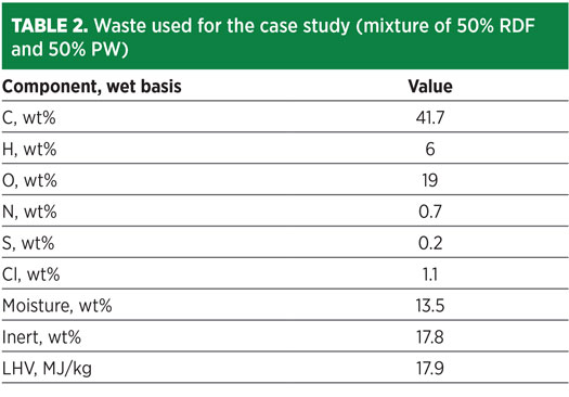
The proposed waste-to-H2 case study is developed around a waste feedstock having an average composition describing a mixture of 50% RDF and 50% PW. The resulting mixture composition is detailed in Table 2.
By applying the process scheme depicted in Fig. 2, the resulting syngas composition at the end of the purification section has a composition as shown in Table 3. The process architecture for H2 production from waste is depicted in Fig. 3.
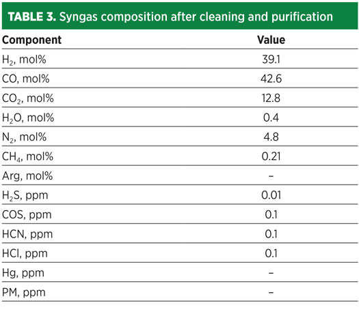
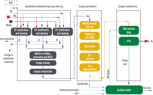
Fig. 3. Waste-to-H2 block diagram.
To increase H2 content, a shift reaction (Eq. 1) is carried out in two intercooling steps. To promote the shift reaction, medium-pressure steam is mixed at the inlet of the shift reactor, operating with a steam/dry syngas ratio of at least of 1.5 to maintain the shift exit temperature below 480°C. Due to the high CO content, a two-stage shift reaction is foreseen to properly control any variation of CO content deriving from the heterogeneous nature of waste.
CO + H2O } CO2 + H2 (1)
The resulting syngas is cooled through heat recovery and cooling water, sent to a gas-liquid separator for condensate removal and routed to a PSA unit. The latter unit allows for the production of H2 at a purity of 99.99%, and the purge gas stream is used as fuel in the auxiliary boiler.
A different approach may be adopted when CO2 capture is required. The high partial pressure of CO2 in the cooled syngas fed to the PSA allows a less energy-intensive capture compared to CO2 capture of hot flue gas. The case study analyzed here is based on a plant architecture without CO2 capture.
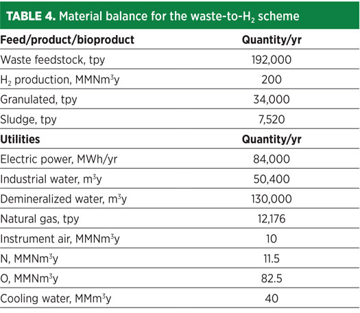
In the proposed architecture, three gasification lines are adopted with an overall capacity of approximately 192,000 tpy of waste delivering around 200 MMNm3/y of H2. Heat and material balance for the proposed scheme were performed using a proprietary simulation program. The key products and byproducts, as well as utilities consumption, are shown in Table 4.
To assess the economic feasibility of the waste-to-H2 technology, an economic evaluation was carried out to estimate CAPEX and OPEX. The overall CAPEX was estimated at approximately €242 MM. A breakdown of relevant costs is shown in Table 5.
To evaluate OPEX and the related H2 cost of production, specific utilities costs have been assumed as outlined in Table 6. On the basis of utilities consumption derived from heat and material balance (Table 4), the OPEX has been estimated at approximately €28 MM/y, with the breakdown shown in Fig. 4.
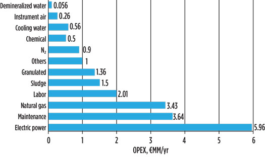
Fig. 4. Estimated OPEX for waste-to-H2 scheme.
The resulting cost of production is strictly related to the waste gate fee. By varying the gate fee from €130/t to €150/t, the resulting H2 cost of production ranges from €0.102/Nm3 to €0.083/Nm3. These values are promising and competitive with the cost of production of a conventional steam reforming process.
For a better understanding of the potential carbon footprint reduction of the proposed waste-to-H2 technology, a simplified lifecycle assessment (LCA) analysis was performed.
The use of waste as feedstock for chemical synthesis allows for the simultaneous fulfillment of two different services: the recovery of waste on one side, and the synthesis of a chemical (H2) on the other. Compared with the conventional routes for waste disposal of incineration and chemical synthesis from fossil feedstock, this system allows for better exploitation of carbon and better CO2 emissions savings. An estimate of CO2 savings from the waste-to-chemicals approach can be quantified using the formulation shown in Eq. 1:
CO2 saving = [(CO2Conv.H2) – (CO2Waste to H2 – CO2Incinerator )] / CO2Conv.H2 (1)
An estimate of CO2 emissions for conventional H2 production takes into consideration that equivalent emission for feed and fuel consumption is around 75% of overall lifecycle emissions. Average feed and fuel consumption for a conventional H2 plant equal to 3,500 kcal/Nm3 of H2 was assumed. The resulting specific emissions for this assumption are approximately 12.6 t CO2/t H2.
Incinerator emissions. The reference value of 2 t CO2/t waste was adopted for the incinerator. Assuming that the distance from the nearest incinerator is equal to 1,000 km, the overall emissions are on the order of 2.1 t CO2/t of waste, which is equal to 22.5 t CO2/t H2.
To properly account for the equivalent CO2 emissions from electric power not produced from waste, an electric energy efficiency of 28% is assumed. It can be calculated that 24 tph of waste with a calorific value of 18 MJ/kg and combustion assisted by natural gas (which assumes 2% of energy content of the waste) would produce around 34 MWe. The latter must be replaced by electric energy from the grid.
Emissions of waste to H2. For the waste-to-H2 plant, the following contributions were taken into account:
Taking into account these estimated contributions, the overall CO2 emissions for the waste-to-H2 plant are on the order of 23.3 t CO2/t H2. The overall savings achieved by the waste-to-H2 plant, according to a simplified lifecycle assessment, are around 90%, corresponding to approximately 202,000 t CO2/yr.
Waste such as refuse-derived fuel (RDF), municipal solid waste (MSW) and plastic waste (PW) may be used as feedstock for the synthesis of a wide range of chemicals. This approach fulfills the waste management hierarchy by taking advantage of waste that cannot be recycled or routed to an incinerator or landfill.
The key to utilizing waste as an alternative feedstock is the primary conversion step, which is based on a high-temperature gasification process carried out in a pure O2 environment and with a temperature profile ensuring certain characteristics for produced syngas.
The case study, based on circular H2 production from waste, showcased a feasible solution from a technical, economic and environmental point of view. A competitive cost of production may be achieved under a gate fee of approximately €130/t–€150/t, which is the average cost for the disposal of such fractions of waste in Italy.
The simplified lifecycle assessment performed for the waste-to-H2 scheme shows high CO2 savings compared to the conventional steam reforming process. The waste-to-chemicals approach also allows for the simultaneous synthesis of a chemical and the recovery of waste. Under the lifecycle assessment scenario, waste enters with a CO2 emissions credit, having avoided a conventional disposal system based on an incinerator.
Under this scenario, the waste-to-H2 scheme accounts for a CO2 emissions savings of approximately 90%. This translates into a potential emissions reduction of around 202,000 t CO2/yr.
Acknowledgments
The authors kindly acknowledge Maire Tecnimont Group and its subsidiary, NextChem, for their research and development support in the field of waste-to-chemicals.
Literature cited
1 EU Directive 2018/851, “Amending directive 2008/98/EC on waste,” Official Journal of the European Union, June 14, 2018, online: https://eur-lex.europa.eu/legal-content/EN/TXT/PDF/?uri=CELEX:32018L0851&from=EN
2 Qu, S., Y. Guo, Z. Ma, W.-Q. Chen, J. Liu, G. Liu, Y. Wang and M. Xu, “Implications of China’s foreign waste ban on the global circular economy,” Resources, Conservation & Recycling, Vol. 144, 2019.
3 World Data Bank, “What a waste,” online: https://datatopics.worldbank.org/what-a-waste/trends_in_solid_waste_management.html
4 Iaquaniello, G., G. Centi, A. Salladini, E. Palo and S. Perathoner, “Waste to chemicals for a circular economy,” Chemistry: A European Journal, Vol. 24, Iss. 46, June 25, 2018.
5 Iaquaniello G., L. Spadacini, A. Salladini and E. Antonetti, “Method and equipment to produce a syngas from wastes, preferably industrial or municipal wastes and their deliverables,” 2018, Patent WO 2018/134853.
6 Salladini, A., A. Borgogna, L. Spadacini, A. Pitrelli, M. Annesini and G. Iaquaniello, “Methanol production from refuse derived fuel: A preliminary analysis on the influence of the RDF composition on process yield,” 2018, online: http://uest.ntua.gr/athens2017/proceedings/pdfs/Athens2017_Salladini_Borgogna_Spadacini_Pitrelli_Annesini _Iaquaniello.pdf.
7 Iaquaniello, G., A. Salladini and E. Antonetti, “A process and relating apparatus to make pure hydrogen from syngas originated from wastes gasification,” Patent WO2018/078661.
8 Iaquaniello, G. and A. Salladini, “A process and relating apparatus to make pure bio-methanol from a syngas originated from wastes gasification,” Patent WO 2018/134853.
9 Howarth, R. W., “Methane emissions and climatic warming risk from hydraulic fracturing and shale gas development: Implications for policy, energy and emission control technologies,” 2015.
10 Green House Gas Protocol, “Global warming potential values,” online: https://www.ghgprotocol.org/sites/default/files/ghgp/Global-Warming-Potential-Values%20%28Feb%2016%202016%29_1.pdf

Giacomo Rispoli joined NextChem SpA from Eni Group in 2020 as a senior executive, and was recently appointed CEO of MyRechemical, which was formed to focus on waste-to-chemicals technology. His long career at Eni covered many positions such as Refineries Manager, Director of R&D and Director of Supply and Licensing.
Mr. Rispoli holds a degree in chemical engineering from the University of Rome.

Annarita Salladini joined Maire Tecnimont subsidiary Processi Innovativi in 2009 and has been involved in R&D projects, feasibility studies and process design packages in the areas of process intensification in hydrogen production, concentrated solar power technology, waste valorization for chemicals and fuels production. She leads a process team at MyRechemical, a NextChem company devoted to the development of waste-to-chemicals applications. She has also coauthored several scientific papers, book chapters and patent applications. Ms. Salladini graduated in chemical engineering in 2004 and received her PhD in chemical and biotechnology innovative processes in 2009 from the University of L’Aquila in Italy.

Alessia Borgogna is a Junior Process Engineer at MyRechemical. Previously, she occupied the same position at NextChem, having joined the company in 2019 after earning her PhD in chemical and environmental engineering. During her PhD studies, she was a visiting student at Karlsruhe Institute of Technology (KIT). Prior to her PhD, she earned an MS degree in chemical engineering in 2016 and a BS degree in chemical engineering in 2014, both from the University of Rome.

Gaetano Iaquaniello is Vice Chairman of NextChem. From 2011, he has also served as Vice President of Corporate Technology for the Maire Tecnimont Innovation Center in the Netherlands, and as CEO of Processi Innovativi Srl. Previously, he worked at KT SpA in a variety of roles. Mr. Iaquaniello is a member of the American Chemical Society and the Vice President of the Italian Society of Chemical Engineers (AIDIC). He has published more than 70 technical papers and is the author of several patents. Mr. Iaquaniello holds a PhD from the U.E.R. des Sciences-Université de Limoges, a graduate degree in chemical engineering from the University of Rome, and an MSc degree in management from the University of London.
Fig. 1. High-temperature gasification reactor.
Fig. 2. Block scheme for gasification and syngas preliminary cleaning and purification.
Fig. 3. Waste-to-H2 block diagram.
Fig. 4. Estimated OPEX for waste-to-H2 scheme.