With a global energy transition underway, interest in H2 as an essential vector in a future energy system is skyrocketing. Presently, 96% of global H2 production is gray or brown H2 produced via reforming and/or gasification of natural gas, oil and coal1 (FIG. 1), with concomitant carbon emissions. For H2 to be part of the decarbonization drive, carbon emissions from gray and brown H2 must be captured and sequestered to produce blue H2. Alternatively, green H2 generation via water electrolysis using renewable energy must be rapidly scaled up and deployed.
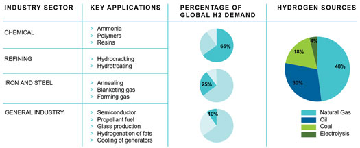
FIG. 1. Global demand and sources of H2 production.1
In Q1 2021, Petrofac delivered a front-end engineering design (FEED) for the Arrowsmith Hydrogen Plant (AHP), a staged development by Infinite Blue Energy (IBE) Group, located in Western Australia, that uses wind and solar energy to produce green H2. Stage 1 of the project, a 25-metric-tpd H2 production facility, is designed with a roadmap to scale up green H2 production to a capacity of 300 metric tpd by Stage 3.
Several challenges were encountered that are not typically faced in the design of gas processing facilities. With H2 on the ascendency, and similar projects expected to proliferate over the next few years, this article will highlight these design challenges and provide recommendations for successfully dealing with them. Some of the recommendations apply to both blue and green H2 production. Also, the deployment of green H2 is explored to identify the critical factors that will promote or hinder the proliferation of this technology.
The challenges described here were addressed in the initial design of Stage 1 of the H2 production facility. The design has since evolved with regard to power generation and H2 offtake requirements.
AHP Stage 1 is designed to produce 25 metric tpd of green H2 from bore water using electrolysis and renewable energy sourced from onsite renewable power generation (FIG. 2).
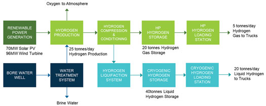
FIG. 2. Block flow diagram of H2 production process.
Bore water is sourced from a local aquifer and stored in a day tank. From the tank, the water is pumped to a water treatment package (WTP) to remove minerals and salts to meet the demineralized (DM) water specification for the electrolyzers. About half of the flowrate of the water into the WTP is discarded as reject water. The demineralized water is routed to a DM water tank with sufficient buffer volume to feed the electrolyzers should the WTP be temporarily unavailable.
The DM water is then pumped to the electrolyzer unit to generate H2 and oxygen. Several electrolyzers from different vendors were considered at the concept stage of this project, and the electrolyzer selection narrowed to either an alkaline electrolyzer or a polymer electrolyte membrane (PEM) electrolyzer.
H2 gas produced from the electrolyzer is first compressed to an appropriate pressure, then conditioned to eliminate any impurities, such as water vapor and oxygen (depending on the type of electrolyzer), to meet the required H2 product specification. The H2 gas exiting the dehydration unit will be stored and offloaded either as high-pressure (HP) H2 gas or as cryogenic liquid hydrogen (LH2).
Both HP hydrogen gas or LH2 can be loaded to trucks for transport to offsite fueling stations and other contracted offtake markets. H2 is transferred via loading connections to trailers or road trains designed to transport either LH2 or HP H2. The loading station also includes provisions for metering and pressure regulation, as required. Presently, the generated oxygen is vented to the atmosphere. The roadmap includes plans to condition and sell the oxygen product in future stages.
The challenges of electrolyzer technology selection, the intermittency of renewable power generation and wastewater management, as well as the approaches to overcome them, are discussed in the following sections.2,3,4,5,6
The challenge: the choice of the electrolysis technology to be used depends on several factors covering technical requirements, economic considerations and regulatory restrictions. These were explored during conceptual design, and two proven types of electrolyzers were considered: alkaline and PEM (TABLE 1).
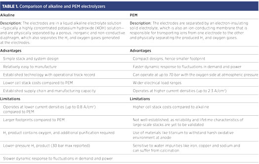
The approach: Three key factors drove the choice of the technology: cost, reliability and application. Cost generally favors alkaline electrolyzers, as they are widely accepted to be less expensive than PEM since the cells are manufactured with inexpensive and easily accessible material. While alkaline electrolyzer cells may be cheaper, a distinction must be made about the comparison of the cell/stack costs and the comparison of overall system costs. The overall system costs, which include H2 product conditioning and plant utility costs, are yet to be rigorously compared.
Regarding reliability, alkaline electrolyzers have been in use for decades with several vendors such as Nel, Thyssenkrupp, Cummins (Hydrogenics) and McPhy offering units with proven service and operating references. Nel, ITM and Siemens commercially offer PEM electrolyzers with operating references. However, for a first-of-a-kind green H2 project of this scale, technology risk is mitigated by choosing the more established technology.
A key advantage of PEM is its faster dynamic response that enables it to robustly handle the intermittency of renewable power generation without a requirement for backup. However, an essential project requirement is that 25 metric tpd of H2 must be contractually delivered to offtakers, a requirement that necessitates a steady power supply. As the power supply to the electrolyzer unit has been designed to ensure steady supply, the flexibility of the PEM unit is not required in this case, negating a key advantage of the technology.
One advantage of PEM units that will require further analysis is the system cost implication of its ability to generate H2 at higher pressures than alkaline units. Alkaline electrolyzers typically operate at atmospheric conditions, so the produced H2 must be compressed and dehydrated for liquefaction or to the required storage pressure. Some PEM electrolyzer manufacturers claim to be able to produce H2 at 70 barg out of the electrolyzer, which is likely to reduce overall system costs.
Ultimately, an alkaline electrolyzer was chosen as the preferred technology for the plant. A process flow diagram is presented in FIG. 3. Potassium hydroxide (KOH), or lye, is used as the electrolyte; when a DC voltage is applied to the electrodes, H2 is generated at the negative electrode while oxygen is formed at the positive electrode. The H2 gas is collected in a duct and routed to an H2/lye separator, and then on to a gas scrubber. The gas scrubber acts as a gas cooler, feed water tank and balancing water seal. The scrubber removes residual KOH droplets from the H2 gas and protects the downstream equipment from alkali deposits and corrosion. The scrubbing water is sprayed evenly on the top of the packed bed in the scrubber, collected in the bottom reservoir and pumped back to the top by the scrubber via a heat exchanger that removes heat from the system and cools the gas. Demineralized water is introduced as make-up water to the bottom water basin of the scrubber. It is from the gas scrubber that feed water is mixed with the lye and then routed to the electrolyzer.
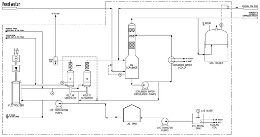
FIG. 3. Process flow diagram of an alkaline electrolyzer unit.
H2 gas produced from the alkaline electrolyzer may contain residual oxygen. The H2 gas is first compressed to an appropriate pressure and then passed through a deoxidizer, a small catalytic reactor that combines any remaining oxygen with the H2 to produce water vapor. The wet H2 gas is then transferred to a dehydration unit, where the water is removed to generate dry H2 at the required product specification, after which it is sent to storage for export.
The challenge: The plant utilizes renewable energy—provided by a 70-MW onsite solar photovoltaic (PV) array and a 96-MW onsite wind farm—to generate green H2. The plant is to be built in a coastal region of Western Australia, a location that is well-suited to both solar and onshore wind power generation, as the climate in this region enjoys extended periods of sunshine and land and sea breezes.
However, both sources of renewable energy are intermittent and fluctuate both on a daily and seasonal basis. Solar PV generates power only during the daytime, depending on the amount of solar irradiance that reaches the panels, which is impacted by cloud cover (FIG. 4). The power generated by wind turbines—provided they are oriented to the correct wind direction—is largely dependent on wind speeds, which vary greatly throughout the day, as shown in FIG. 5.
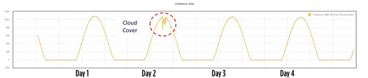
FIG. 4. The 5-d irradiance data from Fulcrum 3D sodar at the Arrowsmith site.
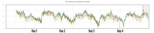
FIG. 5. The 5-d wind speed and direction data from Fulcrum 3D Sodar at the Arrowsmith site.
Therefore, it will be difficult to guarantee sufficient, steady, reliable and continuous power to satisfy the electricity demand from the electrolyzer unit from either or both sources. A reliable backup supply of electricity is necessary to make up for any drop in solar and wind power.
The approach: The Stage 1 plant requires 60 MW of electrolyzer capacity, with about 20% more power to generate 25 metric tpd of H2 gas. To deal with the intermittency of the renewable power-generating assets onsite, the facility is furnished with a connection to the electricity grid, as shown in FIG. 6. Through this connection, any deficiency in renewable energy supply can be topped up by importing green power from the grid to maintain a steady power supply to the electrolyzers and the entire facility.
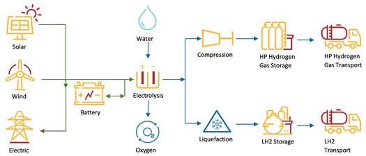
FIG. 6. Arrowsmith Hydrogen Plant schematic.
The green grid connection can also be used to export surplus power that is generated during the day, which provides additional revenue and can also be used to help mitigate against the risk of low H2 demand or low market prices.
In addition, a 6-MWhr battery storage system is provided to attenuate/buffer the renewable power that is supplied to the facility; the system can hold enough power to maintain H2 production in the plant for about 5 min. The battery storage system would also enable a controlled ramp-up and ramp-down of H2 production, a safe shutdown of the plant in the event of a total power failure, and the potential to increase production during periods of low onsite power generation.
The challenge: The project has access to good-quality water from a local aquifer that requires minimal treatment to transform it into the demineralized water required for the electrolyzer units. To generate 25 metric tpd of H2, some 537 metric tpd of aquifer water is required—about half of that amount is converted to demineralized water that is fed to the electrolyzers, while the other half is discarded as reject water from the WTP. The design from the concept stage routed the reject water to evaporation ponds, resulting in a pond area of around 400 m2 to dispose of the water in this part of Western Australia (FIG. 7).
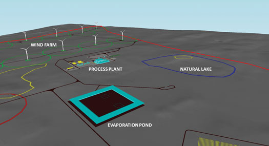
FIG. 7. Site 3D model of evaporation pond and natural lake.
Considering that freshwater is a scarce and valuable resource around the world, the amount of reject water and the area of land required for the evaporation pond are both opportunities for design optimization. In addition, the roadmap plans to expand the facility to produce 300 metric tpd of H2—this will likely require seawater desalination, an energy-hungry process, to provide feed water. Therefore, maximizing the amount of water utilized from the local aquifer would pay rich dividends down the line.
The approach: A systems design approach was pursued that would result in significant reduction of the amount of reject water from the WTP, along with the reduction of the size of the evaporation pond, or preferably its elimination.
Reducing the reject water required close interaction with water treatment specialists and vendors. It is critical to understand the characteristics of the water produced from the aquifer, so the aquifer water was retested. The result from the water analysis was used to optimize the design of the WTP and minimize the amount of reject water, eliminating two-thirds of the amount of reject water initially estimated.
Rather than sending the reject water to an evaporation pond, the reject water was also formulated to meet the local Australian regulatory requirements of total dissolved solids (TDS), which could enable its discharge to ground water. Several options for recycling water are being evaluated.
The availability of freshwater to produce demineralized water may not always be possible in some regions where freshwater is a scarce resource, such as the Middle East. Other water sources, such as seawater, will require more expensive treatment to achieve the water quality needed for electrolyzer units, leading to higher CAPEX and higher utility and energy demands. The disposal of reject water from seawater demineralization can also be subject to stringent environmental regulations, requiring detailed studies focused on its impact on the marine environment. This should be considered when developing green H2 projects in such regions.
Part 2. Part 2 of this article, to be published in the Q1 2022 issue, will examine the challenges and solutions for large-scale H2 storage, equipment supply chain and process safety considerations. It will also examine cost considerations for the deployment of green H2 worldwide.H2T
NOTES
a Petrofac
LITERATURE CITED
1 International Renewable Energy Agency (IRENA), “Hydrogen from renewable power: Technology outlook for the energy transition,” 2018, online: https://www.irena.org/-/media/Files/IRENA/Agency/Publication/2018/Sep/IRENA_Hydrogen_from_renewable_power_2018.pdf
2 DNV, Phast, Process hazard analysis software, online: www.dnv.com/software/services/phast/phast-our-service.html
3 Hydrogen Council, “Path to hydrogen competitiveness: A cost perspective,” January 2020, online: https://hydrogencouncil.com/wp-content/uploads/2020/01/Path-to-Hydrogen-Competitiveness_Full-Study-1.pdf
4 Wood Mackenzie, “Green energy production: Landscape, projects and costs,” 2019, online: https://www.woodmac.com/our-expertise/focus/transition/green-hydrogen-production-2019/
5 International Energy Agency (IEA), “The Future of hydrogen—Seizing today’s opportunities,” 2019, online: https://www.iea.org/reports/the-future-of-hydrogen
6 Scottish Government, “Scottish hydrogen assessment,” December 2020, online: https://www.gov.scot/binaries/content/documents/govscot/publications/research-and-analysis/2020/12/scottish-hydrogen-assessment-report/documents/scottish-hydrogen-assessment/scottish-hydrogen-assessment/govscot%3Adocument/scottish-hydrogen-assessment.pdf

CHET BILIYOK is a Chartered Process Engineer with 16 years of experience in process design, project execution, technical consultancy and R & D across the energy industry. He has drawn on previous experience working in oil and gas to deliver projects in renewable/low carbon H2, carbon capture, utilization and storage (CCUS)
and waste-to-fuels, recently serving as the Process Lead during FEED of the Arrowsmith Green Hydrogen Project. Dr. Biliyok has authored more than 20 peer-reviewed journal articles and presented his work at major international conferences. He is based in Petrofac’s Woking, UK office as the Technical Director of Petrofac’s New Energy Services and seeks to deliver solutions that enable organizations to thrive in a low-carbon energy future.

MICHAEL CZARNECKI is a Chartered Chemical Engineer with 17 years of experience working in process design and project engineering management across the energy industry. He works as a Study Manager supporting Petrofac’s Engineering & Consultancy services team in Petrofac’s Woking, UK office. Mr. Czarnecki recently project-managed the Arrowsmith Green Hydrogen FEED Project. This project involved the integration of wind turbine and solar PV technology to electrolyze H2 from raw water. He has a keen interest in low-carbon projects and new technologies and is applying his experience of working within the onshore and offshore oil and gas sectors to new energy projects.

AHMED DAR has more than 25 years of engineering experience in the oil and gas, petrochemicals and sulfur management sectors. He has worked on a variety of international projects for major engineering contractors and operating companies. His experience encompasses all project phases, from project proposals to conceptual design, feasibility studies and FEED to detailed engineering. He is a subject matter expert in sulfur recovery unit design, operations, troubleshooting and performance optimization. Mr. Dar joined Petrofac in 2018 and works as a Consultant Process Engineer supporting Petrofac’s Engineering & Consultancy team in the Woking, UK office. He recently provided process engineering and design support on the Arrowsmith Green Hydrogen FEED project and is interested in renewable energy technologies and carbon capture and sequestration. Mr. Dar earned an MS degree in advanced chemical engineering and is a Chartered Engineer.

STEPHEN J. GAULD is the Managing Director at Infinity Blue Energy, based in Perth, Australia. He has more than 20 years of experience in the oil and gas sector working for some of the largest global service companies and operators, such as Baker Hughes GE, ENI, ExxonMobil, Chevron, RocOil and Woodside. Mr. Gauld is very experienced in managing project delivery and cash flow and gained a wealth of experience field testing and developing state-of-the-art rotary steerable and logging while drilling technology. In the last five years, he has delivered several renewable energy projects from design, civils and construction through commissioning and now leads Australia’s first commercial-scale green H2 plant north of Perth.