Infrastructure and distribution
H2 blending in natural gas pipelines—technological challenges and opportunities
H2 is expected to play an important role in the energy transition, reinforcing the use of renewable energy resources and providing a low- to no-carbon footprint. H2 is an abundant source of energy in the universe, including the nuclear fusion reactions of our own sun; however, its utilization as an energy agent is limited, due to the challenges of producing and transporting it for use as an energy carrier. This article reviews the potential for transporting H2 through natural gas pipelines, including the associated technical challenges and opportunities.
The mixing of H2 with natural gas can significantly reduce greenhouse gas emissions since the combustion of H2 produces no greenhouse gases—this is under the assumption that the H2 is produced from renewable energy resources (wind, solar, biomass) or fossil resources with carbon capture and storage (CCS). The social and environmental benefits associated with the hydrogen blend component to natural gas are obvious: it reduces carbon oxides (COx), sulfur oxides (SOx), nitrogen oxides (NOx) and particulate matter emissions.
An economic incentive exists for the use of renewable energy surplus, enhancing the sustainability of natural gas supply systems, since natural gas can be utilized also after the fossil transient era. Moreover, an extended operational life of conventional power plants that are presently fueled by natural gas can be achieved.
H2 has a high heating value of ΔΗΗ2 = 120,000 kJ/kg, and a low density of ρΗ2 = 0.089 kg/m3, compared to natural gas, where indicative values are ΔΗNG = 48,000 kJ/kg and ρNG = 0.76 kg/m3 at ambient conditions. The heating value of the mixture depends on the composition of the natural gas, H2 purity and the percentage of H2 in the mixture, and can be obtained using Eq. 1:
Hmixture = ΔΗmix + ∑xi × Hi (1)
where:
Hmixture = Total enthalpy of the system after mixing
ΔΗmix= Enthalpy of mixing
Xi = Mole fraction of component i
in the system
Hi = Enthalpy of pure component i
Therefore, a 10% per mole fraction blending of H2 in a natural gas pipeline results in an increase of enthalpy of 2% for the gas mixture.
Although blending ratios are usually expressed in volumetric percentages, the H2 share to the increase of gas mixture heating value and, subsequently, to the potential carbon dioxide (CO2) emissions savings, is low due to the low volumetric energy density—roughly 1/3 of 1 of methane (CH4).
For energy offtakers, it is important that the combustion conditions and Wobbe index are ensured within the range of the end-users’ operational conditions (i.e., a gas turbine or power plant). Because the mixture can be enriched to higher percentages of H2, it is possible to extract the H2 downstream of the gas pipeline section.
In the case of high H2 percentages in the gas blending, applicable extraction technologies separating the H2 downstream are discussed here.
Pressure swing adsorption (PSA). PSA, shown in FIG. 1, operates utilizing adsorption media that have a correlation of surface adsorption vs. gas partial pressure. As the gas pressure increases, the concentration of adsorbed species on the surface increases. The substances adsorbed in case of the gas mixture are CH4, CO2 and CO, whereas the H2 passes through the adsorption bed.
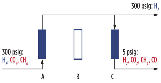
FIG. 1. Pressure swing adsorption (PSA) schematic.
Since the adsorption bed is saturated for a designated time for a designated flow and pressure condition or duty, a standby configuration of beds is used so that the saturated bed is regenerated during the filtering process.
The method is suitable for H2 separation at flowrates of 50 Nm3/hr–200,000 Nm3/hr at an elevated pressure of 150 psig–300 psig. While a good H2 purity level is ensured, a small percentage is expected to be adsorbed on the surface of the medium and then removed during the bed regeneration.1
Membrane separation technology. This technology works efficiently with high concentrations of H2, ensuring good efficiency with certain membrane technologies that can reach 100% purity with adequate membrane selection. Due to the high differential pressure required across the membrane for H2 recovery, the flow should be compressed to high pressures; therefore, this technology is suitable for high-pressure pipelines.
Electrochemical H2 separation. Known as H2 pumping, this technology is based on the gas mixture compression. However, it is not as mature as PSA or membrane separation.
Most pipeline materials for transmission distribution and service for gas networks are carbon steel and polyethylene plastic pipes, depending on the operating pressure of the system.
Research is being conducted regarding the compatibility of the materials—H2, when contained under high partial pressure in combination with high temperatures, can induce cracking to the metal surface, also known as H2 embrittlement (FIG. 2).
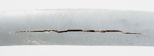
FIG. 2. H2-induced cracks.
The higher stresses induced by higher operating pressures inside pipes of low or moderate yield strength (API 5L, A, B, X42, X46, etc.) can raise concerns for the durability of the material.
Generally, carbon steel is acceptable for H2 service and operating temperatures below 250°C and moderate partial pressures, as shown in the modified Nelson diagram from API 941 (FIG. 3).2
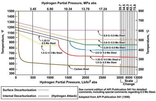
FIG. 3. Material suitability for H2 application.
It is known that the degradation of polymer materials in normal environmental conditions is caused by UV radiation, chemical attack and thermal breakdown. With an H2 attack, little or no interaction between H2 gas and polyethylene is expected. Considering that H2 does not provide radicals that can cause polymer breakdown, it is expected that H2 does not promote polymer degradation.
As the smallest molecule, H2 is very permeable and has a great tendency to leak through pipes, valves, seals and gaskets. The permeation rates for H2 are four to five times faster than CH4, and the volume leakage rate of H2 is three times the volume leakage rate of natural gas; therefore, the accumulation of H2 in confined space can raise safety issues.
Adding H2 into natural gas modifies the properties of the gas mixture. Subsequently, it is necessary to calibrate the gas meter when measuring blending mixtures at various H2 levels.
The threaded and flanged connections are considered potential leakage sources and should be minimized, and the threaded connections should be avoided, leaving no exposed points of possible leakage.
With flanges, gasket reliability is a critical factor. Spiral-wound gaskets—a serrated solid metal ring sandwiched between a soft/deformable sealing material—should be used for lower pressure classes, whereas “rtj” (confined metal) gaskets are more suitable for the higher pressures.
The valves included in H2 blending systems should be high quality (body seals and stem packing) and with a tight shutoff; check valves should be avoided.
The occurrence and the severity of H2 defects on metallic materials depend on the type of the materials, H2 concentration and operating parameters.
H2 cracking begins once the service conditions (high pressure and high temperature) allow the H2 diffused into the steel to react with the carbon and carbides in the steel. Under fatigue loading, the period of time until mechanical damage can be detected is commonly referred to as “incubation time,” which defines the lifetime of the steel pipeline.
According to API 941,2 the incubation times for carbon steel piping in different operating conditions are stipulated in FIG. 4.

FIG. 4. Incubation time for high-temperature H2 attack damage of carbon steel (non-welded or welded with post-weld heat treatment) in high-temperature H2 service.
Safety. H2 can ignite in a broader range of conditions related to natural gas, so the probability of ignition and subsequent risk (risk = probability × severity) for the blended pipelines is higher.
Risk factors depend on the H2 concentration (i.e., 20%, 50%), the type of gas pipeline system (transmission, distribution), the pipeline material and the operating conditions.
Nevertheless, gas network systems pose a lower risk of severe accidents compared to similar scale’s energy systems, such as petroleum, nuclear and hydropower. The major failure factor in natural gas pipeline networks is leakage. Failure causes for leak incidents include corrosion; material and construction defects related to defective welds, stripped threads, improper backfill for plastic pipes; natural catastrophes; excavation damage; equipment malfunction; and operation offset.1
The H2 transition is related to the restructuring of electricity generation supply within the next decades, considering the environmental regulations that are applied due to climate change.
Assuming CO2 capture and storage—and considering its capabilities to produce greater H2 quantities utilizing processing such as steam reforming (STR), autothermal reforming (ATR), partial oxidation and coal gasification in industry, petrochemicals and power plants—blue H2 can ease the transition to green H2 production, which requires more time to be developed at a large scale. Additionally, CH4 decomposition through pyrolysis leaving solid carbon without producing greenhouse gas emissions remains under development for commercial utilization. Presently, blue H2 is 1.5–2 times less expensive than green H2, and the mentioned technology can be developed much faster.3
CO2 emissions remain the primary challenge, but innovative technologies will continue to improve the industry’s environmental footprint.
For example, future demand for H2 as an energy carrier in the Netherlands is analyzed in FIG. 5, which forecasts a total estimated demand of 430 PJ (120 TWh) per year will be reached in 2050, which is substantial and sufficient to build a hydrogen chain.4
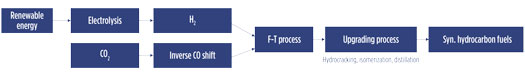
FIG. 5. Predictions for Dutch H2 demand in 2050 vs. the consumption sector.
Six sectors for H2 demand in 2050 are shown; for two of them, it is assumed that the imported H2 is relatively cheap, resulting in higher domestic demand. A more conservative estimation asserts that approximately 250 Pj/yr of domestic H2 demand is a realistic case. Likewise, industry is calculated to use 180 Pj (1,500 kt) of H2.5 Both quantities require significant production, which can be achieved by the conversion of gray H2 to blue H2, as well as the utilization of green H2.5
Green H2 is produced by renewable power (e.g., wind farms and photovoltaic plants). The production of H2 can be obtained with the use of electrolyzers, which can run during periods of excess power production without introducing this power to the electricity grid due to the limited comparison of production and demand.
The present generation cost of green H2 ranges from $2.5/kg–$4.5/kg. The challenge is that it is more expensive to produce green H2 than blue H2. Mitigation and investment cost reduction are expected through the introduction of commercial incentives (i.e., subsidization), environmental regulations and continued technology maturity.
LITERATURE CITED
1 Melaina, M. W., O. Antonia and M. Penev, “Blending hydrogen into natural gas pipeline networks: A review of key issues,” NREL/TP-5600-51995, March 2013.
2 American Petroleum Institute (API) 941, “Steels for hydrogen service at elevated temperatures and pressures in petroleum refineries and petrochemical plants,” API Recommended Practice, February 2016.
3 Noussan, M., P. P. Raimondi, R. Scita and M. Hafner, “The role of green and blue hydrogen in the energy transition—A technological and geopolitical perspective,” Sustainability 2021, December 2020, online: https://doi.org/10.3390/su13010298
4 Berenschot and Kalavasta, “Climate neutral energy scenarios 2050 (in Dutch),” BK study, 2020, online: https://www.rijksoverheid.nl/documenten/rapporten/2020/03/31/klimaatneutrale-energiescenarios-2050
5 Schroot, B., “The Netherlands: a blue hydrogen economy now will ease a transition to green,” April 2021, online: www.energypost.eu

Giannis Vallios serves as a member of the board of directors and Gas, Water & Energy Division Director of METRON SA–Energy Applications. He is now involved with the energy transition projects, including hydrogen utilization. He has 30 yr of experience in natural gas, oil and energy projects in the fields of design and detailed engineering and project management, integrating and delivering complete systems for fuel processing, controlling and custody metering to the international market. Mr. Vallios earned a Diploma degree in mechanical engineering at the University of Patras in Greece, an MSc degree in energy and thermal power from Manchester University in
the U.K., and an MSc degree in environmental engineering from Hellenic Open University.