SPECIAL FOCUS: PATHWAYS FOR SUSTAINABLE HYDROGEN
E. CARTER and A. HICKMAN, Honeywell UOP, Des Plaines, Illinois
The urgency to limit global warming to 1.5°C is intensifying. Global leaders are developing decarbonization strategies to meet the goals of the Paris Climate Accord. Climate modeling indicates that to meet this ambition, rapid, aggressive decarbonization must start now, and global CO2 emissions must reach net zero by 2050. This will require a multidimensional strategy, employing cost-effective decarbonization tools including improved efficiency, circularity, deep electrification with renewable power, migration to low carbon intensity or renewable fuels and feedstocks, and carbon capture and storage (CCS).
One challenge is the so-called “hard-to-decarbonize” sectors, such as industrial, residential and heavy transportation. Reducing emissions in these sectors requires either large-scale and distributed deployment of CCS or switching to renewable or clean-burning fuels. Hydrogen is a promising fuel because it generates no greenhouse gas emissions at the point of use. Demand for H2 is expected to increase up to 10-fold, from 75 MMtpy today, as it replaces natural gas, diesel and jet fuel.1
For H2 to be a critical vector for the energy transition in the coming decades, its production must be decarbonized. Today, H2 is produced mainly from fossil fuels, resulting in 800 MMtpy of CO2 emissions—2% of total global CO2 emissions. This traditional production scheme is called “gray” H2 and has lifecycle greenhouse gas emissions of 9–11 kg CO2 equivalent (CO2eq)/kg H2, depending on the method of production and transportation distance.2
Several methods exist to produce H2 with low carbon intensity, including the addition of CCS for so-called “blue” H2 (1.2–1.5 CO2eq/kg H2 at 90%–98% CCS rates), use of renewable feedstocks such as biogas or biofuels (1–3.3 CO2eq/kg H2), or water electrolysis using 100% renewable electricity for so-called “green” H2 (0.3–1 kg CO2eq/kg H2). Even 100% renewable electricity does not have zero lifecycle greenhouse gas emissions because energy is required to produce wind turbines and solar panels.
All three of these low-carbon-intensity H2 production pathways can achieve very low lifecycle emissions compared to gray H2. Each will have a role in supplying the H2 demands of the future, as shown by the almost daily announcements of new blue and green H2 commercial projects and studies around the world.
The lowest lifecycle emissions cited previously are for 100% wind-powered electrolysis of water, coming in at 0.3 kg CO2eq/kg H2. Although multi-GW projects have been announced, green H2 is an industry in its infancy, with the world’s largest operating green H2 plant having an electrolyzer capacity of 20 MW. To generate the same amount of H2 as a typical refinery steam methane reformer (100 ktpy or 125 MMsft3d) with renewable-powered electrolysis of water, approximately 50 times that electrolyzer capacity would be required (1 GW), along with an equal amount of installed renewable power.
This large amount of renewable power capacity is best used in a strategic decarbonization pathway to replace fossil power first, as it can have 2.5–6 times the decarbonization impact. Furthermore, despite significant cost reductions over the past 10 yr, green H2 production remains expensive, at 4–6 times the cost of steam methane reforming with CCS.3
In contrast, blue H2 can address the urgent challenge of decarbonization as the ready-now, commercially proven, and economic alternative to CO2-emitting processes. The H2 production and carbon-capture technologies that enable blue H2 are commercially proven at scale and economical at CO2 prices that are available in Europe and North America today. The technology is well-suited to serve existing and emerging H2 markets.
In the near term, decarbonizing H2 production of existing refining and chemical feedstock assets can be expedited with bolt-on carbon-capture revamps. Over the next decade, new low-carbon-intensity H2 plants will be built to meet the steep growth in demand for clean H2 fuel.
The main infrastructure hurdle for blue H2 is the widespread development of carbon-sequestration facilities for permanent geological storage. Many worldwide projects are in various stages of project lifecycles, amounting to approximately 40 MMtpy of CO2 storage capacity. By 2050, if all H2 demand (550 MMtpy) were met by blue H2, then the CO2 generated will consume < 0.02%/yr of current assessed global high- and medium-confidence underground CO2 capacity.4 Ongoing development of CO2 infrastructure for transportation and sequestration is needed in tandem with blue H2 and other CCS decarbonization projects.
Blue H2 plays an important role in leading the way to decarbonization. This article explores technology options for blue H2 production, including the revamp of existing assets and greenfield installations. Technology selection and operating parameters have a role to play in maximizing CO2 reduction impact while delivering the H2 and CO2 products on spec and at the lowest cost of production.
Most existing H2 production plants for refining, chemical and agricultural use employ a steam methane reformer (SMR) to convert hydrocarbon feeds, such as natural gas and steam, into synthesis gas, which comprises H2, CO, CO2, unconverted methane and a small amount of inerts. To maximize H2, the synthesis gas is cooled and shifted in a water-gas shift reactor to convert CO and water to H2 and CO2.
In a gray H2 scheme, the shifted syngas is separated in an H2 pressure swing adsorption (PSA) unit to generate a high-purity H2 stream and a low-pressure tail gas stream that is sent to the reformer furnace as fuel, with additional natural gas to supply heat for the endothermic SMR reaction. Accordingly, all the carbon from the natural gas exits the system as CO2 in the furnace stack.
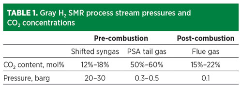
To reduce the carbon emissions of an existing gray H2 asset, CO2 can be captured from three locations:
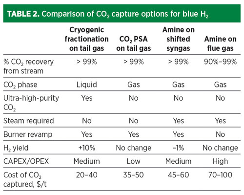
The cost of CO2 capture depends on the pressure and concentration of the CO2 in the source stream (TABLE 1), plus the product specifications for the H2 and CO2. The most cost-effective location to remove CO2 is from the pre-combustion streams. The CO2 can be removed by a variety of means, including solvent-based absorption, PSA or cryogenic fractionation.
The option that provides the lowest overall cost of CO2 captured is cryogenic fractionation, which also achieves additional high-purity H2 yield (FIG. 1). In this option, the H2 PSA tail gas is compressed, dried, condensed and fractionated, resulting in a high-purity liquid CO2 stream. Combining separation and liquefaction in a single unit operation saves utilities when a liquid product is required.
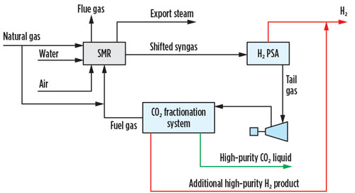
Fig. 1 SMR retrofit CO2 capture option 1.
Recent advances include further separation of the CO2 fractionation overhead in a second, smaller PSA unit that operates with a novel process cycle that enables recovery of 90% of the remaining H2. Overall, 99% H2 recovery from the SMR is possible with this scheme. This additional H2 recovery offsets investment in CO2 capture, reducing the net cost of carbon captured to $20/t–$40/t. This retrofit does not require any revamp to the existing H2 PSA, can be operated “on” or “off” without impacting the SMR operation, is solvent-free, has a smaller footprint than an amine unit, requires no steam usage in the CO2 recovery steps, and is guaranteed to meet high-purity CO2 product specifications with 99+% CO2 recovery. This combination of technologies has been selected for a large U.S. CCS project for clean H2 production at Wabash Valley Resources LLC in West Terre Haute, Indiana.
An alternative option for CO2 capture from the PSA tail gas is a CO2 PSA unit. A CO2 PSA unit can be installed on the shifted syngas or the H2 PSA tail gas, although the latter is preferred primarily due to a simpler revamp and ease of operation in the event that the CO2 capture unit is bypassed (FIG. 2). The CO2 PSA is the lowest CAPEX and OPEX carbon-capture option and can remove 99% of the CO2 in the pre-combustion stream, but the extracted product is low pressure and low purity, requiring drying and liquefaction, or contaminant polishing via catalytic oxidation, followed by drying and multiple stages of compression to be transport-ready.
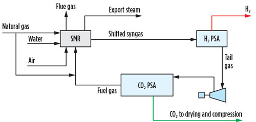
Fig. 2 SMR retrofit CO2 capture option 2.
The third option for CO2 recovery is amine-based solvent capture of the shifted syngas. This established technology can achieve 99% CO2 removal from the shifted stream (FIG. 3). However, this option requires the use of steam for solvent regeneration. The carbon emissions associated with steam generation erode the net benefit. Furthermore, by removing the CO2 upstream of the H2 PSA, the overall H2 recovery will be eroded. This deficit could be mitigated with PSA adsorbent reload and cycle modification; however, such changes would make it very difficult to continue operation if the CO2 removal unit were bypassed.
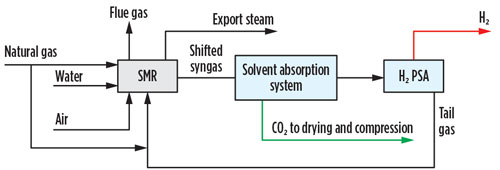
Fig. 3 SMR retrofit CO2 capture option 3.
Finally, the low-pressure CO2 product requires drying and multistage compression or liquefaction to be transport-ready. For end-users that want gas-phase CO2 and are long on steam, an amine unit is a reliable, proven choice for CO2 recovery, albeit at a higher cost of capture than tail gas recovery (TABLE 2).
In all cases, the composition of the fuel gas recycled to the SMR furnace is significantly altered. As a result, burner revamp is required. CO2 removal from the fuel gas requires advanced burner technology for stability and to achieve low NOx emissions. Advanced burners are customized to the furnace licensor’s specifications and can be revamped to enable low-carbon-intensity H2 production, including the ability to rapidly switch between multiple fuels in the event the CO2 system is bypassed.
Adding any of the three pre-combustion CO2 removal technologies discussed to a conventional SMR unit will reduce emissions by up to 60%. For a typical refinery SMR producing 100 ktpy of H2 (125 MMsft3d), up to 520 ktpy of CO2 can be captured, which is enough to make a significant impact in many near-term CO2 reduction pledges.
To further reduce emissions, CO2 must be eliminated from the furnace flue gas. Two options exist to reduce flue gas emissions:
The flue gas stream is the most expensive stream to scrub CO2 due to the low pressure and low concentration. Current best-in-class solvent technology for flue gas capture results in costs 2–4 times more per metric t of CO2 captured than pre-combustion capture due to the low CO2 partial pressure and solvent degradation. To reduce the cost of SMR flue gas CO2 capture, advanced solvents with high solvent stability, improved mass transfer properties, and low heat of regeneration are needed.
Flue gas emissions also can be reduced through SMR revamp options that minimize furnace firing and use of an H2-rich fuel. Several options can result in greater than 90% CO2 capture without the need for expensive post-combustion capture. These options include operating the reformer at high methane conversion in a pre-reformer, a primary reformer and, optionally, a secondary gas heated reformer in series or in parallel; eliminating excess steam export; using a structured catalyst insert; adding low-temperature water-gas shift to minimize CO content in the shifted syngas; removing the pre-combustion CO2 from either the syngas or the tail gas, and diverting a slipstream of H2-rich fuel to the furnace.5 These revamp options to minimize furnace firing may be invasive for existing assets, but this type of optimized SMR design that concentrates CO2 for pre-combustion capture is expected to play a significant role for new assets.
For low-carbon-intensity H2 projects to be viable, government policy must provide a business case for investment—which can come in the form of funding, incentives, trading schemes, credits and even taxes on CO2. Recently, CO2 price structures, national decarbonization strategies, and public- and private-sector investments in clean energy have been seen globally.
Now is an active time for CCS in the U.S. because of the enhanced 45Q federal tax credit signed into law in 2018, with the IRS issuing final guidance in August 2020. The final guidance provides the clarity and assurance that CCS developers and investors need to move beyond the preliminary stage. The tax credit provides up to $35/t of CO2 for enhanced oil recovery (EOR) and $50/t of CO2 for permanent geological storage for CO2 captured in facilities that meet thresholds in terms of size, and where construction begins by the end of 2025.
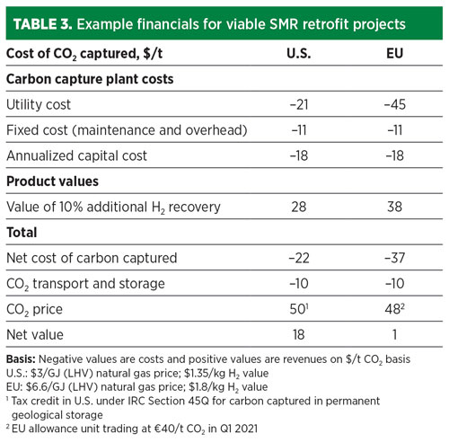
Another example is in the EU, where the Emissions Trading System (ETS), a cap-and-trade scheme, saw CO2 prices rise to more than €40/t ($48/t) in Q1 2021. These carbon prices are sufficient to make blue H2 projects commercially attractive today. TABLE 3 shows that retrofitting an SMR with cryogenic fractionation on tail gas can provide solid payback in both the U.S. and EU.
Growth in H2 demand is expected to come largely from its use as a CO2-free energy source to partially displace natural gas for heat and power in industrial and residential sectors where gas infrastructure currently exists. Today, about 2,000 Bm3 of natural gas is used for heat and power in a highly distributed user base. A portion of this volume can be substituted by H2 without major infrastructure modifications while still using the distribution network for natural gas. Greenfield design of these H2-as-fuel plants can be customized to deliver the lowest cost of H2 production and the lowest cost of CO2 avoided. H2 is also expected to be used as an energy source in the transportation sector. H2 can be used in a fuel cell to power forklifts, cars, trucks and even locomotives, ships and planes.
Each of these end-use applications requires that the H2 meet certain purity and pressure specifications (TABLE 4). In the refining industry, H2 is typically purified with PSA units that can deliver 99.9+% purity at more than 90% recovery for use in hydroprocessing, where catalysts are sensitive to CO poisoning. For use in ammonia synthesis, the syngas typically is scrubbed of CO2 and then methanated and washed with nitrogen, or purified by PSA.
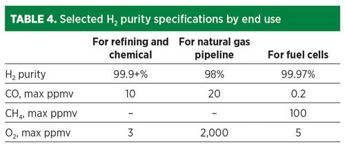
In the emerging fuel cell markets, ISO 14687 sets specifications for H2 fuels for fuel cells requiring 99.97% H2 purity, 0.2 ppmv CO maximum and 5 ppmv O2 maximum. An industry standard does not yet exist for H2 used in natural gas networks. The Hy4Heat program in the UK conducted a cost-benefit analysis in 2019 and proposed an H2 purity specification for domestic and commercial heating applications of more than 98% purity, a CO max of 20 ppmv in line with short-term exposure limits, and an O2 max of 0.2% to reduce corrosion rates and maintain pipeline integrity.6
Similarly, the captured CO2 product must meet certain phase and purity specifications based on its sequestration or utilization. CO2 pipelines for enhanced oil recovery require injection pressures of 153 bar at ambient temperature, but only a fraction of all CO2 capture sites will have direct access to a CO2 pipeline. Many will need to transport the CO2 to injection sites—either for pipeline transport or for geological storage. In these cases, liquid phase ship transport of CO2 (7 bar and –50°C) is often required. Some sequestration sites have adopted strict purity specifications with ppm level limits on CO, O2 and H2S.
Blue H2 producers aiming for carbon intensities approaching that of green H2 will need to choose among SMR technology that is optimized to minimize radiant firing while using H2-rich fuel, autothermal reforming (ATR) and partial oxidation (POX). The latter two technologies offer a similar advantage to the optimized SMR design of enabling more than 90% CO2 capture without costly, post-combustion capture, but they achieve this by eliminating the furnace and its associated flue gas at the expense of requiring pure O2 as a reagent and reduced production of H2 per mole of methane processed.
In all three of these options, greater than 90% CO2 capture can be achieved with a single capture step on a pre-combustion stream. The CO2 capture technologies covered in the SMR retrofit analysis are equally applicable for new unit installations, irrespective of reformer selection. The most appropriate pre-combustion technology for carbon capture and H2 purification will depend greatly on the required phase, purity, pressure, storage and means of transport for both the CO2 and the H2 (FIG. 4).
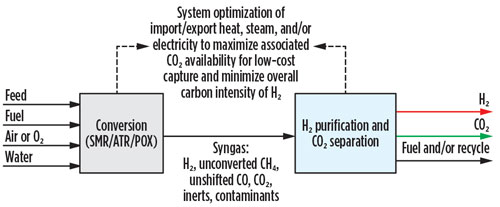
Fig. 4 New blue H2 unit landscape.
Takeaway. Hundreds of companies and countries have committed to achieving net-zero emissions in support of the Paris Climate Accord. Retrofitting existing SMR assets with carbon-capture technology is a ready-now, commercially proven and significant step on the journey to net zero. With technology innovations such as the cryogenic fractionation system on the PSA tail gas with additional H2 yield leading to a cost of carbon captured as low as $20/t of CO2, these projects make financial sense today in many areas with an established price on carbon.
As the decade progresses, new blue assets in the form of SMR, ATR and POX will be built to realize the potential of H2 to address “hard-to-decarbonize” sectors. Escalating the carbon price, coupled with emerging technological advances, will drive investment. Depending on the end uses of the H2 and CO2, the technology of choice for the syngas separation will vary. Through thoughtful pairing of carbon capture and H2 purification technology, economic differentiation can be achieved, delivering a significant step in the CO2 countdown to net zero.H2T
LITERATURE CITED
1 Hydrogen Council, Study Task Force, “Hydrogen scaling up: A sustainable pathway for the global energy transition, 2017, Online: https://hydrogencouncil.com/wp-content/uploads/2017/11/Hydrogen-scaling-up-Hydrogen-Council.pdf
2 Hydrogen Council, “Hydrogen decarbonization pathways: A life-cycle assessment,” 2021, Online: https://hydrogencouncil.com/wp-content/uploads/2021/01/Hydrogen-Council-Report_Decarbonization-Pathways_Part-1-Lifecycle-Assessment.pdf
3 International Energy Agency, “The future of hydrogen,” 2019, Online: https://www.iea.org/reports/the-future-of-hydrogen
4 Page, B., et. al, “Global Status of CCS 2020,” Global CCS Institute, 2020, Online: https://www.globalccsinstitute.com/wp-content/uploads/2020/12/Global-Status-of-CCS-Report-2020_FINAL_December11.pdf
5 Jakobsen, D. and V. Åtland, “Concepts for large scale hydrogen production,” Master’s thesis, Norwegian University of Science and Technology, 2016, Online: https://ntnuopen.ntnu.no/ntnu-xmlui/handle/11250/2402554
6 DNV GL, Department for Business, Energy and Industrial Strategy, “Hy4Heat (WP2) Hydrogen purity and colourant hydrogen purity—Final report,” No. 10123173, Rev. 05, 2019, Online: https://static1.squarespace.com/static/5b8eae345cfd799896a803f4/t/5e58ebfc9df53f4eb31f7cf8/1582885917781/WP2+Report+final.pdf
AMANDA HICKMAN is a Principal R&D Scientist at Honeywell UOP, where she leads the development of breakthrough technology platforms. She joined UOP in 2011, after receiving a PhD in chemistry from the University of Michigan. Since arriving at UOP, Dr. Hickman has worked as a technical leader and project manager in the refining and petrochemical industry, with experience in adsorptive separation and contaminant removal, biodegradable surfactants and carbon capture for low-emission hydrogen production.
BETH CARTER is the Senior Business Manager for Clean Hydrogen at Honeywell UOP. In this role, she leads the commercialization of Honeywell UOP’s hydrogen and carbon-capture technologies as key enablers of the global energy transition. She has been with UOP since 2008, spending her early career in field service and engineering, followed by leadership positions in R&D focused on the design, optimization and commercialization of new process technologies. Ms. Carter received a BS degree in chemical engineering from Northwestern University in Evanston, Illinois and is a licensed Professional Engineer in Illinois.
Fig. 1. SMR retrofit CO2 capture option 1.
Fig. 2. SMR retrofit CO2 capture option 2.
Fig. 3. SMR retrofit CO2 capture option 3.
Fig. 4. New blue H2 unit landscape.