BERG, D. J. BENAC and D. SHAFFER, Baker Engineering and Risk Consultants, San Antonio, Texas
Considerable investment has been allotted to the research and development of renewable and alternative forms of energy in the private sector, in academia and by governments around the world. The impetus for the recent interest in these energy forms is to provide an alternative to fossil fuels by deploying new technology that enables these alternative and renewable forms of energy to address climate change. Examples of these types of technology include battery energy storage systems; electrochemical fuel cells; and even new and novel types of batteries, including graphene and lithium metal batteries.1,2 These technologies are at different stages of development and vary from commercially available to theoretical research.
Technology utilizing hydrogen fuel has been successfully implemented as an alternative energy source globally.3 H2 fuel cells have been available in commercial form in vehicles and in power generation applications for decades. New electrochemical fuel cells utilizing ammonia fuel are a promising new technology alternative to direct H2 and hydrocarbon fuel cells. Recent interest in ammonia anode fuel cells has sparked investment in this technology as a potential replacement for petroleum-powered vehicles and power generation.4 Ammonia also provides promise, as it may provide a source of H2 fuel for H2 technology. However, accommodating increased usage of ammonia anode and even H2 fuel cells using ammonia as the H2 source requires significant increases in ammonia production capacity globally.
Creating large-scale infrastructure for ammonia and H2 fuels requires an objective assessment of the associated operational and lifecycle risks. It is important to recognize that consideration of all potential hazards and threats throughout the supply chain is a multidisciplinary undertaking to ensure successful deployment and safe operation of the supply chain. On the production side of the supply chain, ammonia process equipment is susceptible to hazards and threats in the form of materials degradation and metallurgical damage mechanisms from the process fluids handled by ammonia production and handling equipment.
This article highlights three common metallurgical damage mechanisms that can result in potentially dangerous equipment failures and costly downtime in ammonia process equipment if not properly managed. Additionally, this article discusses methods to identify and diagnose these damage mechanisms, susceptible materials, inspection methods for identifying damage, and mitigation options and important points of consideration for operating and maintaining such equipment. The goal is to connect various parts of the ammonia production process and process variables with how they may influence the damage mechanisms of the production equipment discussed in this article.
It is important to discuss the steps and units in the ammonia production process. For the synthesis of ammonia, a carbon/H2 source, water and nitrogen are fed into the front end of the plant to provide a feed stream of fresh syngas: H2 and nitrogen in an approximate ratio of 3:1.
Normally, the feed stream to ammonia synthesis (the back end) is free of CO and CO2, and may contain small amounts of water and inerts such as methane and argon. In a cryogenic purifier process, the final front-end steps remove impurities that make the methanation and molecular sieve/NH3 washing steps unnecessary.
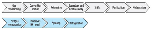
FIG. 1 shows the units in the ammonia process, with the top row indicating the front-end units and the bottom row showing the back-end units.
Most equipment in the ammonia production process are essentially pressure vessels and piping leading to storage tanks with pressure boundaries constructed of metallic materials. All materials of construction used in the ammonia industry are susceptible to degradation and various types of damage mechanisms. While it may be possible to select materials of construction that are completely resistant to attack by the process fluids, such an approach is often impractical.
Carbon and low-alloy steels are the most commonly used materials of construction for process equipment in the ammonia industry. These materials offer a suitable combination of strength and ductility, and are capable of safely operating in the temperature ranges often seen in the ammonia industry. However, carbon and low-alloy steels are susceptible to corrosion damage mechanisms.
Stainless steel alloys and nickel-based alloys, depending on the types selected, provide resistance to corrosion attack in environments containing carbonic, acid and chlorides. However, these materials are not impervious to corrosion.
Copper alloys are highly susceptible to corrosion attack in ammonia environments and should be avoided for equipment in the pressure boundary or in direct contact with process fluids in the ammonia industry.
Three metallurgical damage mechanisms commonly affect ammonia equipment and are discussed in relation to process variables, process equipment and materials of construction:
Awareness of mechanisms that can damage equipment is essential in developing solutions to properly inspect the equipment, mitigate damage and prevent failure. The pertinent damage mechanisms are also input for evaluations regarding fitness-for-service as the mechanism and rate of attack need to be understood to determine the remaining life. For a proper risk-based inspection (RBI) program or during a hazards analysis, the appropriate mechanisms are identified so that the probability of failure can be determined in addressing reliability issues.5
HTHA is a form of degradation caused by H2 reacting with carbon to form methane in a high-temperature environment. When steel is exposed to H2 at elevated temperatures, H2 will diffuse into the alloy and combine with carbon to form small pockets of methane. The methane is trapped at grain boundaries and in voids and does not diffuse out of the metal. Once accumulated, the methane expands, forming voids that can lead to initiated cracks in the steel. An example of such fractures, viewed in the microstructure of a carbon steel pipe weld, is shown in FIG. 2.6 High-strength, low-alloy steels are particularly susceptible to this mechanism, which leads to embrittlement of the bulk parent metal. The embrittlement in the material can result in a catastrophic brittle fracture of the asset.7–10
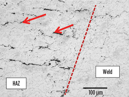
Fig. 2 H2 damage observed in the carbon steel line at the heat-affected zone (HAZ). Decarburization and fissuring region caused by H2 depleting the iron carbides. Nital etch. (Original magnification: 200 times).6,12
Susceptible materials include high-strength, low-alloy steels (legacy C–½Mo steels), plain carbon steels, non-post-weld heat-treated (PWHT) welds, and copper alloys. Alloy steels such as 1.25Cr–0.5Mo provide resistance for milder HTHA conditions, but the alloy must be matched properly to the process conditions that the metal sees. API RP 941 provides guidance to aid in materials selection for fixed equipment operating in environments with H2 partial pressures at elevated temperatures and pressures.11 This guidance also can be useful to materials engineers and process engineers alike, as knowledge of both process conditions and the materials of construction will provide information on an asset’s susceptibility to this particular damage mechanism.
The most obvious equipment concerns are any equipment exceeding normal operating temperatures or operating window limits, specifically carbon and low-alloy steel vessels and piping operating at temperatures that are above the API RP 941 Nelson curve values. Aging plants should be mindful of API RP 941 Nelson curve changes and should determine whether process changes or HTHA mitigation strategies may be implemented. HTHA is not a concern in stainless steel vessels; however, stainless steel-lined vessels with the possibility of high H2 partial pressure behind the liner are a concern.
H2 content is high in the ammonia process streams—up to 67% on a volume basis—and it is important to evaluate for HTHA potential where the temperatures rise above 204°C (400°F) for carbon steel materials. The H2 content should be considered on a wet gas basis, which may reduce the risk susceptibility for equipment prior to condensation of water vapor occurring after the shift unit.
Typical concerns start with the shift unit and equipment through the ammonia synthesis loop, where temperatures are above 204°C (400°F). However, HTHA may be present in other areas, such as secondary unit pressure shells due to refractory failure, which can lead to high temperatures on steel pressure shells. Referring to FIG. 1, HTHA also can be a concern throughout the ammonia process, including equipment in the shift units (both high and low shift), methanation and synthesis loop.
Synthesis loop equipment, particularly converters without furnace stress relief or operating at high temperatures on the pressure shells, and startup heater coils are also vulnerable points for attack. Additionally, hot spots from refractory failures can occur in the primary reformer outlet, in secondary reformer and waste heat boilers, molsieves and pressure envelopes. Thermal imaging inspections or other means are used to monitor hotspots on refractory lined pressure shells of HTHA (or creep) in susceptible materials.
Hester and Benac provide details regarding an investigation conducted into a carbon steel effluent cooler header piping rupture, installed in an ammonia converter and synthesis loop, that occurred 5 yr after a change in operating conditions. The process temperature was increased from 232°C (450°F) to 510°C (490°F), and the operating pressure was decreased from 29 MPa (4,200 psig) [14.5 MPa (2,100 psig) H2 partial pressure] to 23.4 MPa (3,400 psig) [11.7 MPa (1,700 psig) H2 partial pressure]. This process change placed the carbon steel pipe above the API RP 941 Nelson curve temperature for carbon steel at the corresponding H2 partial pressure. The piping rupture was found to have a brittle fracture appearance.
Failure analysis revealed that HTHA was the damage mechanism that caused the pipe rupture. This example case demonstrates the vulnerability of this portion of the ammonia process if material limits are exceeded and how process changes can create the potential for eventual failure.6,12 Uncontrolled materials substitutions can also lead to failures.
Several inspection methods may be successfully used to identify HTHA:
Note: These methods are highly dependent on the technique and skill level of the inspector. False positives and negatives are possible with improper techniques and inadequate skill levels. This is why it is essential to consult qualified inspection experts to assist in inspection efforts.
One of the most critical ways to mitigate the potential for HTHA is for plant engineering to review plant processes, U1 materials of construction and operating conditions to identify potential HTHA risks with H2-containing equipment. An important component of this includes conducting an engineering review of pressure, H2 partial pressure and temperature. Operating with safety margins—e.g., 10°C (50°F) below the API RP 941 Nelson curve—also can provide additional assurance. Engineering should establish integrity operating limits for all vulnerable equipment. Materials control programs are essential, including guards against uncontrolled materials substitutions, and active positive materials identification programs for incoming materials and field/retro components.
If feasible, aging plants should consider reviewing potential replacement of equipment with higher-alloy material that is less susceptible to HTHA, according to the API RP 941 Nelson curve for desired operating conditions. This review should include determining whether welded equipment or piping was post-weld heat-treated, and if not known, assume non-post-weld heat-treated and operate at lower temperature and pressure. Installing temperature indicators at critical locations to monitor actual temperatures and performing regular thermography measurements can help ensure that operating windows and limits are not exceeded, or identify those that need to be addressed.
SCC occurs when a susceptible material is exposed to a specific environment and tensile stress. The combination of these three factors leads to brittle fracture of normally ductile materials at stress levels within the normal operating range. Multiple types of environmentally assisted SCC exist, including chloride SCC, amine SCC and ammonia SCC.
Nitrate SCC may come from exposure to nearby nitric acid, ammonium nitrate, or urea emissions that hydrolyze to form nitrate. During stress corrosion cracking, the material may not show signs of wall loss or pitting, but fine cracks will form within the material or on the surface. This process has serious implications on the utility of the material because the applicable safe stress levels are drastically reduced in the corrosive medium. Some environments of concern are potash, nitrates and sulfides.7,13,14,15
The most common cracking mechanism detected in ammonia storage tanks, spheres and other process equipment is ammonia SCC (NH3 SCC), which is a function of ammonia exposure in conjunction with an O2 source—typically O2 or CO2. NH3 SCC can occur at atmospheric liquid ammonia conditions of –33°C (–27°F), but at faster rates at higher temperatures under pressurized ammonia conditions. Tanks used for transporting liquid NH3, like rail tank cars, tank cars, barges and vessels, are also susceptible to SCC.
For ammonia equipment, susceptible materials to NH3 SCC include carbon steel, low-alloy steels and stainless steels exposed to high O2 levels or chlorides. Residual stress within parts increases the potential for SCC; therefore, post-weld heat treatment (PWHT) of carbon steels can lower the probability of SCC. PWHT is often used to mitigate NH3 SCC in pressurized equipment. NH3 storage tanks are also particularly susceptible to NH3 SCC, as they may lack PWHT and be more susceptible to O2 contamination in the presence of NH3. High hardness can be a concern, as higher hardness material is more susceptible, with the heat-affected zone (HAZ) and areas with localized stress being the most vulnerable. Vapor spaces may be preferentially attacked due to higher temperatures and the higher presence of O2 that is not protected by water in the NH3 liquid phase.
For NH3 equipment, chlorides may be present in insulation or cooling waters, both of which can result in SCC of stainless steels. Affected NH3 process units include susceptible materials in the convection unit, such as headers exposed to chlorides in insulation; primary reformer inlet pigtails; the synthetic loop startup heater coils, which may be exposed to atmospheric SCC promoters; and exchangers with seawater or cooling water with high chloride content.
Several inspection methods can be used to identify SCC cracks:
NH3 SCC is mitigated by avoiding air, O2 and CO2 sources, and by the addition of small amounts of water (0.2%) where O2 may be present. The design and operation of atmospheric tanks should avoid vacuum conditions that would pull air into the vapor space. Vapor spaces are more susceptible due to higher temperatures and the higher presence of O2 that is not protected by water in the ammonia. Especially where PWHT is not practical, such as atmospheric storage tanks, materials are specified with both minimum and maximum hardness, and suitable weld materials are chosen. For chloride SCC, keeping steam temperatures below 60°C (140°F) can prevent cracking in stainless steel heat exchangers.
The loss of ductility determines whether a brittle fracture could occur. The conditions, mechanisms and/or degradations that cause the loss of ductility must be considered. Brittle fracture occurs when a material breaks with little to no plastic deformation. Typically, a fracture occurs rapidly, with no warning and with less energy needed than a ductile fracture.
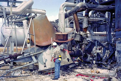
FIG. 3 shows a brittle fracture that occurred suddenly in an NH3 plant.17,18
Most metals undergo a ductile-to-brittle transition in fracture toughness with decreasing temperature. Carbon steel and low-alloy steel materials will undergo a transformation from ductile-to-brittle behavior as the material temperature drops, resulting in low toughness at low temperatures and increasing the hazard of brittle fracture. Increasing the thickness of a material can result in higher ductile-to-brittle fracture temperatures. A typical impact energy curve, or Charpy curve, is shown in FIG. 4.8,16
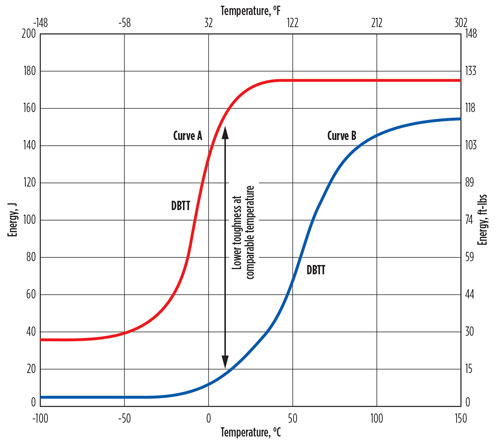
Fig. 4 Charpy impact curves showing the transition from a ductile behavior to a more brittle behavior as the temperature decreases.17
Brittle fracture can occur in the presence of a small flaw in a low-toughness material when stresses are sufficiently high. It is a concern in NH3 equipment since NH3’s boiling point of –34°C (–29°F) is slightly less than the common carbon steel minimum design metal temperature (MDMT) of –29°C (–20°F). Refrigerated services typically require material specifications and/or Charpy impact testing to avoid introducing brittle fracture hazards to the plant.
A limited portion of the NH3 process sees these temperatures in normal conditions. NH3 process units where brittle fracture is a concern include the synthesis loop, syngas compression, refrigeration, molsieves, NH3 wash and cryogenic purification. Equipment such as chillers, flash drums and NH3 product separators may be susceptible to reaching temperatures below the ductile brittle transition temperature (DBTT) for steels. Depressurization will lower temperatures, and repressurization controls may be needed to ensure that the stresses are acceptable. In older plants, refrigeration chillers may not meet existing guidelines, or they may be operated at lower-than-DBTT temperatures.
NH3 in refrigeration service or in cryogenic storage systems typically operate in a cold condition. NH3’s saturation temperature at atmospheric pressure is –34°C (–29°F). There are, however, a number of instances and situations where brittle fracture failures are a concern in the NH3 industry. The use of carbon or low-alloy steel, thick-walled loop equipment is likely to have increased MDMT. Auto-refrigeration can reduce temperatures below the MDMT.16,17,18
Pressure vessels using steels pre-1987 materials of construction and older equipment produced prior to ASME code revisions recognizing plane strain impacts on DBTT can be more susceptible to brittle fracture.19 Use of inferior, vintage-grade steels such as SA212, SA285 and SA225—which are prone to brittle fracture under certain conditions—are more vulnerable. Carbon steels and low-alloy steels with low toughness and an existing flaw or crack, and materials that contain residual stresses due to improper stress relief or that do not undergo PWHT, are more susceptible. Normalized steel is less susceptible to brittle fracture than steels having undergone other treatment.
Operationally and from a design standpoint, pressurized ammonia systems that normally operate above –29°C (–20°F) can quickly decrease in temperature below the minimum allowable when the system is depressurized. Additionally, thicker wall vessels created for high pressure, such as those found in the syngas compression, synthesis loop and purge units, are more susceptible. These vessels can have significantly higher minimum design temperatures for the same materials due to plane strain, and are more likely to fall below their minimum allowable temperatures at ambient conditions. Liquid nitrogen exposures (including nitrogen purge equipment and process equipment under poor purge controls) are a hazard, and liquid nitrogen supply contractors may introduce a brittle fracture hazard to the site if using improper equipment.
To prevent brittle fracture, inspection methods should focus on the initiation of cracks. After initiation, ensure that the crack size is stable to avoid fast and unstable fracture. Methods using API 579-1/ASME Fitness for Service, Part 9 and other specifications can be used for this assessment.20,21 Typical inspection methods to search for cracks include:
Options to mitigate brittle fracture include following up-to-date ASME codes for carbon steel pressure vessel materials that are subject to temperatures of less than –29°C (–20°F). Selecting proper materials for equipment and piping based on establishing the appropriate MDMT, including the use of fine-grained carbon steels with proven toughness by impact testing, nickel-containing low-alloy steels with 9% Ni steel at temperatures as low as –196°C (–320°F), austenitic stainless steels (i.e., 300 series), and aluminum alloys (because they have no ductile-to-brittle transition when cooled), are essential to preventing brittle fracture.
Performing PWHT to relieve stress can be used to improve the DBTT of the equipment. Using good welding procedures and filler metals to avoid porosity and lack of fusion are helpful, as well. Performing a cold embrittlement fracture assessment, as outlined in API 579-1/ASME Fitness for Service FFS-1, Part 3, or completing a fracture mechanics assessment per API 579-1/ASME Fitness for Service FFS-1, Part 9 for cracks found during inspection can help mitigate brittle fracture.
Finally, for operators and process engineers, use of operating procedures and temperature controls to keep equipment above the DBTT when pressurized are critical to preventing brittle fracture.
Hydrogen technology is expected to play a particularly important role in the future of renewable and alternative forms of energy. Ammonia technology and the NH3 process are expected to see substantial growth to accommodate existing technologies, as well as new technology currently in development. With the growth and expansion of the ammonia cycle and the creation of new facilities to increase production, ensuring safe operation and mitigating hazards is essential.
Safe equipment design, operation and maintenance of NH3 equipment and assets is a collaborative effort between ammonia process engineers, mechanical design and asset integrity engineers and materials engineers. For mechanical and materials engineers, it is important to have a collaborative understanding of the ammonia process parameters—e.g., operating pressures, temperatures, chemical compositions of process fluids, etc., to make informed materials selection decisions. For the process engineer, it is important to have a general understanding of how decisions to change process parameters during a revamp to improve efficiency, for example, may impact the assets of a particular material of construction.
Implementation of the right programs and bringing in knowledgeable technical experts with experience in the hazards and threats within this industry are essential to ensuring that accurate assessments are completed and that safety, longevity and proper mitigation of hazards are guaranteed. To this end, the authors’ consultancy created a joint industry program (JIP) with numerous participants that are operators in the ammonia industry. The 2020–2021 JIP focuses on improving safety and reliability in the ammonia and fertilizer industry. The first year of the JIP included the identification of damage mechanisms and mitigation options for plant equipment in the ammonia process. The overall plan for the JIP provides for subsequent-year studies that will address other safety and reliability issues, including damage mechanisms and mitigation options for other fertilizer industry processes including urea, nitric acid and ammonium nitrate.22 H2T
LITERATURE CITED
1 Koohi-Fayegh, S. and M. A. Rosen, “A review of energy storage types, applications and recent developments,” Journal of Energy Storage, Vol. 27, February 2020.
2 Kim, H., H. D. Lim, J. Kima and K. Kang, “Graphene for advanced Li/S and Li/air batteries,” Journal of Materials Chemistry A, Iss. 1, 2014.
3 Abe, J. O., A. P. I. Popoola, E. Ajenifuja and O. M. Popoola, “Hydrogen energy, economy and storage: Review and recommendation,” International Journal of Hydrogen Energy, Vol. 44, Iss. 29, June 7, 2019.
4 Lim, D. K., A. B. Plymill, H. Paik, X. Qian, S. Zecevic, C. R. I. Chisholm and S. M. Haile, “Solid acid electrochemical cell for the production of hydrogen from ammonia,” Joule 4, November 18, 2020.
5 Baker, J., D. J. Benac and D. Shaffer, “Damage mechanism reviews and mitigation methodology for ammonia equipment,” Safety in Ammonia Plants and Related Facilities Symposium, 2019.
6 Benac, D. J. and M. W. Hester, “Elevated temperature failure mechanisms in ammonia plant equipment—Reducing the risk of failure” Safety in Ammonia Plants and Related Facilities Symposium, 2013.
7 American Petroleum Institute (API), API 571, Sec. 3.36, “Damage mechanisms affecting fixed equipment in the refining industry,” 3rd Ed., March 2020.
8 Urzendowski, M. and D. Chronister, “Unexpected cases of HTHA in gasoline desulfurization units,” API Equipment and Standards Meeting, May 2011.
9 Chemical Safety Board (CSB) Bulletin 2005-04-B, “Positive material verification: Prevent errors during alloy steel systems maintenance,” October 2006.
10 Prueter, P. E., R. Jones, J. Hess and J. DeLuca, “Managing the risks associated with a hydrotreater reactor with possible high-temperature hydrogen attack,” Proceedings of the ASME 2019 Pressure Vessels and Piping Division Conference, San Antonio, Texas, July 14–19, 2019.
11 API Recommended Practice 941, “Steels for hydrogen service at elevated temperatures and pressures in petroleum refineries and petrochemical plants” 8th Ed., 2016.
12 Hester, M. W. and D. J. Benac, “Reducing the risk of HTHA failures,” World Fertilizer Magazine, October 2019.
13 Loginow, W., “Stress corrosion cracking of steel in liquefied ammonia service—A recapitulation,” National Board of Pressure Vessel Inspectors, National Board Bulletin, January 1989.
14 Russell, A. M., “Testing and recommended practices to improve nurse tank safety,” Phase 1, U.S. Department of Transportation, FMCSA-RRR-13-032, October 2013.
15 “Stainless steels in ammonia production,” Committee of Stainless Steel Producers, AISI, November 1978.
16 Macejko, B., “Is your plant vulnerable to a brittle fracture?” Hydrocarbon Processing, November 2014.
17 Benac, D. J., D. Shaffer and D. Wood, “Managing cold temperature and brittle fracture hazards in ammonia-related industries,” Safety in the Ammonia Plants and Facilities Symposium, 2015.
18 Benac, D. J., N. Cherolis and D. Wood, “Managing cold temperature and brittle fracture hazards for pressure vessels,” Journal of Failure Analysis and Prevention, February 2016, Vol. 16.
19 American Society of Mechanical Engineers, “Boiler and Pressure Vessel Code, Section 8: Rules for Construction of Pressure Vessels, Division 1,” New York, New York, 2017.
20 API 579-1/ASME Fitness for Service FFS-1: “Assessment of existing equipment for brittle fracture,” Part 3, June 2016.
21 British Standard Institute, BS7910, “Guide on methods for assessing the acceptability of flaws in metallic structures,” December 2019.
22 Baker, J., D. J. Benac and D. Shaffer, “Ammonia and fertilizer industry joint industry program—A resource to manage damage mechanisms and mitigation options,” World Fertilizer, 2020.

SEAN BERG works in BakerRisk’s San Antonio, Texas office as part of the Investigation and Materials Group. He has a background in both mechanical engineering and metallurgical and materials engineering, and is a registered professional engineer practicing in both disciplines. As a university professor, he has taught university coursework and conducted research in each of these areas of engineering. With 10 yr of experience as an engineer, Dr. Berg has expertise in structural and mechanical integrity of fixed and rotating equipment, fitness-for-service assessments, failure analysis of plant and refinery equipment, high-pressure high-temperature (HPHT) drilling and production systems, and forensic investigation of property damage and determining origin and cause of losses resulting from fire, water, weather and external forces. Dr. Berg is also a specialist in batteries and battery materials, with in-depth expertise in battery energy storage systems and associated hazards.

DANIEL J. BENAC works at BakerRisk’s San Antonio, Texas office in the Materials Engineering Group. As a registered professional metallurgical engineer in the state of Texas, Mr. Benac is a specialist in structural integrity and material issues, failure analysis of plant equipment, materials evaluations and materials selection for designs. He has more than 35 yr of experience investigating and solving structural integrity problems for plant equipment.

DOROTHY SHAFFER is a subject matter resource for ammonia-related production and terminal facilities. She has 20 yr with a major ammonia producer in production, process engineering, project engineering and as Director of Risk and Reliability, and 15 yr of consulting work on mechanical integrity programs, process safety and risk evaluation work. Mrs. Shaffer’s background bridges gaps among process, operations and mechanical integrity programs in ammonia-related fields.
Fig. 1. Typical ammonia production process flow diagram.
Fig. 2. H2 damage observed in the carbon steel line at the heat-affected zone (HAZ). Decarburization and fissuring region caused by H2 depleting the iron carbides. Nital etch. (Original magnification: 200 times).6,12
Fig. 3. Brittle fracture of a pressure vessel in an ammonia plant.
Fig. 4. Charpy impact curves showing the transition from a ductile behavior to a more brittle behavior as the temperature decreases.17