R. V. SCHNEIDER, Chiyoda Corp., Houston, Texas; and D. KUROSAKI and M. OKI, Chiyoda Corp., Yokohama, Japan
Is hydrogen the fuel of the future? This most-abundant element in the universe has, for many years, played a key role in the international space program and in more down-to-earth applications for refinery upgrading and chemicals production, such as methanol and ammonia. However, production of renewable H2 at a competitive cost, and the transport thereof, present key issues that are being studied and progressed by almost every developed country in the world.
The benefits are obvious: H2 can be made from many and varied processes and burns completely and cleanly, with only water vapor as a byproduct of combustion. Japan has progressed its H2 economy by developing detailed plans to replace nuclear energy and fossil fuel combustion with clean-burning H2, both at the industrial and residential scale. Europe has, for several years, harnessed wind energy for power production; this technology also can be used for H2 production where desired. A project is already underway in Germany to provide H2 to an existing refinery for fuels upgrading, using wind energy to power the electrolyzer that will produce the renewable H2.
In the U.S., California leads the way with initiatives that are not only policy-based but are also state law. Almost 9,000 fuel cell personal vehicles traverse the California freeways today, with fuel available for a 5-min fill-up from 42 stations. By 2025, it is anticipated that there will be many more fuel cell electric vehicles (FCEVs) and many more refueling stations in use, along with H2 use in city buses and heavy transport vehicles, supported by state laws driving these developments.
Northeastern states in the U.S. will likely follow California’s lead, and provincial energy ministries in Canada’s eastern and western regions are already progressing initiatives that are modeled, to a degree, after those in California. While the mid-section of the U.S. would not be a likely place for H2 to take root, a U.S. Department of Energy (DOE)-sponsored study is already underway in oil- and gas-rich Texas to consider and demonstrate H2 as a fuel for data center backup power and mobility uses. Additionally, the Texas study will consider how the Port of Houston may benefit from material transport using H2, similar to what is already being done in Long Beach, California.
In this article, the authors introduce liquid organic H2 carrier (LOHC) technology and how it has been applied to the world’s first global H2 supply chain demonstration project.
Demand for H2 in the U.S. alone is more than 11 metric MMtpy. At present, the two largest uses for H2 are hydroprocessing in refineries (57%) and chemicals production (38%, ammonia and methanol production combined). Future additional demand will be driven by a number of applications:
Estimates project that U.S. H2 demand will grow to about 17 metric MMtpy by 2030 and to 63 metric MMtpy or more by 2050. Considering mobility applications alone, several automakers are producing personal FCEV cars—Toyota (Mirai) (FIG. 1), Honda (Clarity) and Hyundai (Nexo). While less than 10,000 FCEVs are on U.S. roads at present, projections call for up to 150,000 FCEV sales by 2025 and more than 1 MM sales by 2030.
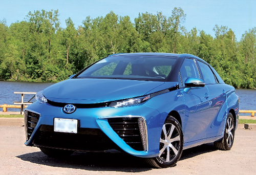
Fig. 1. Toyota’s Mirai FCEV passenger car, produced starting in 2014.
A personal FCEV requires a fill-up of approximately 5 kg of H2. Considering the current proven range of these vehicles and average annual use, the 2030 FCEV H2 demand in California alone can be calculated in the range of 250,000 metric t for passenger cars only. When heavy-duty vehicles for material transport are factored into the mix, demand will be considerably higher.
By 2030, fuel cell-powered forklifts used by large-warehouse companies, such as Walmart and Amazon, could number more than 300,000. Total added H2 demand by 2030 could be approximately 3 metric MMt, although this number is expected to increase by around 45 metric MMt by 2050—a significant volume.
Investment in the H2 economy is forecast in the range of $8B–$10B by 2030, and hundreds of thousands of new jobs could be created. While these numbers are not concrete, they impart a sense of scale for the potential of H2 in the U.S. and other forward-thinking countries.
Expected benefits from the integration of H2 into the U.S. energy picture include not only decarbonization, but also a bolstering of the overall economy, preservation and strengthening of the U.S. energy position and obvious improvements to health, the environment and quality of life. Benefits on a more global basis would be commensurately similar.
While the future for H2 looks bright, production, transportation, distribution and a host of associated infrastructural issues need to be considered. Assuming H2 availability, how to get it from where it is made to where it is most needed (and at a reasonable cost) is of paramount interest.
Historically, H2 has been transported either as a compressed gas in tube trailers or as a cryogenic liquid. Both methods have pros and cons, but transportation selection and cost are ultimately determined by how much H2 must be transported and over what distance.
Prior studies undertaken for localized distribution have considered and compared these conventional methodologies with newer, more promising options of transporting H2 bound by a chemical carrier, known generically as a liquid organic H2 carrier (LOHC).
FIG. 2 shows how H2 is liquefied to 20K (–253°C/–423°F) for transport as a cryogenic liquid. This is an energy-intensive operation that uses around 30% of the contained H2 energy to complete the liquefaction process. The cryogenic H2 is then transported from the liquefaction point to the point of use by truck. As per U.S. Department of Transportation (DOT) limitations on truck transport of liquefied H2, approximately 4,000 kg of H2 can be transported per truckload. At the delivery site, the liquid can be cryo-pumped to the dispensing point for subsequent vaporization. At present, transportation of liquid H2 is available only by truck; therefore, the scale of transportation is limited, and further technology development is required for large-scale liquid transportation by ship.
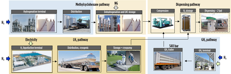
Fig. 2. Process flow showing how H2 is liquefied for transport as a cryogenic liquid, is transported as a compressed gas or is transported within an organic carrier (LOHC).
Alternatively, H2 at approximately 540 bar (7,830 psi) can be transported by tube trailer from a terminal to a dispensing point where final compression (to around 700 bar/10,000 psi) is accomplished prior to ultimate utilization. U.S. DOT regulations also limit the amount of H2 that can be transported per tube-trailer truckload to approximately 1,050 kg of H2 per truck.
Lastly, the LOHC option may be considered as a viable alternative. LOHC is a suitable technology for large-scale, long-distance H2 transportation, or for large-scale or daily to seasonal H2 storage, as will be discussed in more detail in this article. In all of these cases, the distance of transport, the volume of material being transported and the distribution particulars will drive the best choice for the particular H2 application at hand.
The SPERA Hydrogena process is an H2 storage and transportation technology for large-scale and long-distance transportation. H2 is chemically fixed to toluene and converted to methylcyclohexane, according to the reaction shown in FIG. 3. Methylcyclohexane is a convenient carrier for H2, as it is easy to store and transport under ambient temperature and atmospheric pressure. In the SPERA process, H2 is stored and transported in large-scale quantities at a competitive cost, since cryogenic liquefaction or compression to very high pressures is not required.
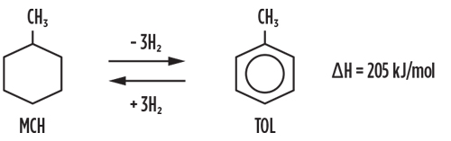
Fig. 3. Chemical reaction formula used for the SPERA Hydrogena process.
The SPERA process is based on a simple process configuration. Methylcyclohexane and toluene react in fixed-bed, tubular-type reactors in the vapor phase. FIG. 4 shows simplified process flow diagrams of the hydrogenation and dehydrogenation processes for the overall SPERA process. In the hydrogenation process, toluene feed is vaporized in the vaporizer (1) and mixed with H2 including recycle gas. The mixed feed is superheated to the reaction temperature (2) and then enters the top of the reactor (3), which is a fixed-bed, tubular reactor charged with a semi-conventional hydrogenation catalyst. In the reactor tubes, toluene reacts with H2 to produce methylcyclohexane.
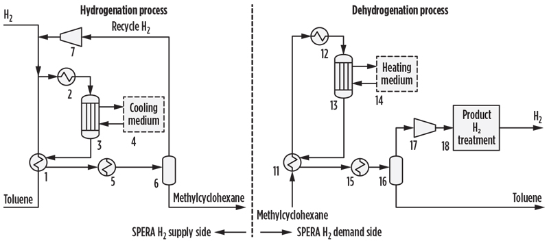
Fig. 4. Hydrogenation and dehydrogenation processes for the SPERA process.
Hydrogenation of toluene is an exothermic reaction. The generated heat is removed by cooling water to control the reaction temperature, and the heat is subsequently recovered as medium-pressure steam, which can be further utilized as needed. The generated steam is clean energy without carbon emission. The effluent gas from the tubular reactor is cooled, the condensed methylcyclohexane is separated (6) from the recycle gas, and the liquid product (methylcyclohexane) is sent to storage tanks. Recycle gas is then returned to the reactor after being mixed with fresh H2 feed. Very high product yield is achieved in this step, which contributes to the efficiency of the SPERA process. Toluene losses within the process are minimal.
Produced methylcyclohexane is then transported to the site of H2 use. H2 is recovered from the methylcyclohexane via catalytic dehydrogenation. The dehydrogenation process can be described as follows: The methylcyclohexane feed is vaporized in the vaporizer (11) and super-heated in the charge heater (12) before entering the catalyst-packed tubes of the dehydrogenation reactor (13). This reactor is a tubular, quasi-isothermal reactor design similar to that employed in the hydrogenation process. The SPERA dehydrogenation catalyst was specially developed in-house for this process. Since dehydrogenation is an endothermic reaction, an external heating source is required. Typically, a hot oil system is applied (14) to supply the necessary reaction heat.
The dehydrogenation plant is ideally co-located within an existing complex where available waste heat at a suitable temperature level can be utilized. Reactor effluent gas is cooled to separate H2 and condensed toluene (16). In the reactor, methylcyclohexane is reconverted to toluene and H2. The recovered H2 is separated from the toluene and is subsequently compressed and purified, if necessary, to meet relevant product H2 specifications (18). Toluene is then transported back to the site of the hydrogenation plant for re-hydrogenation.
Key to the success of SPERA was the development of a dehydrogenation catalyst that was not only robust, but also exhibited superior selectivity and stability. As depicted in FIG. 5, methylcyclohexane conversion of greater than 95% was eventually achieved at a selectivity of 99.9%, which provides for a very low level of reaction byproducts.
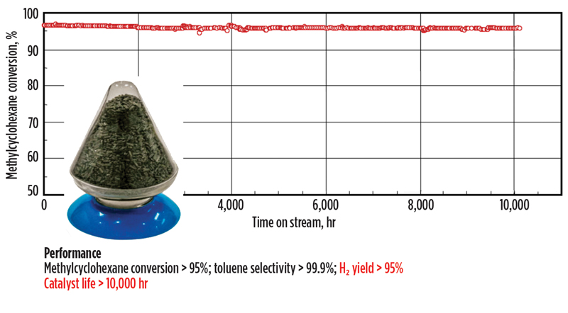
Fig. 5. Dehydrogenation catalyst development and performance.
Accelerated, long-term testing showed remarkable stability even after 10,000 hr onstream. Commercially, a catalyst life of 2 yr could be reasonably expected. Once a suitable candidate catalyst was developed, the next steps to eventual commercialization included scale-up for manufacturing and pilot-level demo of both the catalyst and the equipment envisioned for the SPERA process.
From April 2013–November 2014, 10,000 hr of pilot plant operation were successfully completed, and the expected performance and life of the catalysts were confirmed. In the pilot-scale test facility, methylcyclohexane and toluene were continuously dehydrogenated and rehydrogenated at a consistent rate of 50 Nm3/hr of H2 (FIG. 6).
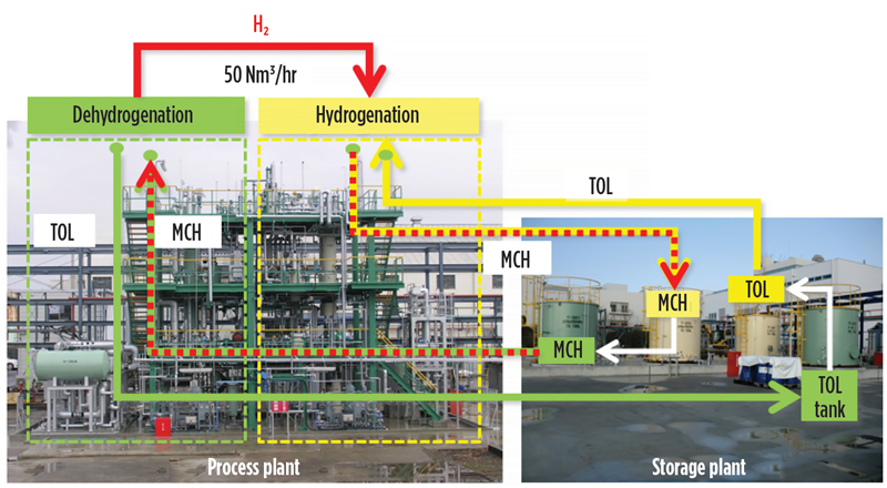
Fig. 6. Demonstration plant in Yokohama, Japan showing dehydrogenation/hydrogenation for the SPERA process.
Chiyoda, along with its partners Mitsubishi, Mitsui and Nippon Yusen, established the Advanced Hydrogen Energy Chain Association for Technology Development (AHEAD), and subsequently initiated the world’s first global H2 supply chain demo project, for which construction was completed in 2020.
Global supply chain. AHEAD’s key project is aimed at demonstrating the transport of H2 via a chemical carrier over a distance of 5,000 km, from the production site in Brunei to Tokyo Harbor. The demo project is funded by the Japanese New Energy and Industrial Technology Development Organization (NEDO).
The production and shipment of methylcyclohexane in ISO containers were started in early 2020. FIG. 7 shows the flow of material from Brunei to Tokyo Harbor and the return of toluene to Brunei. H2 was produced at a preexisting process plant site in Brunei through conventional steam reforming of natural gas; however, the SPERA process can be applied to H2 from any production means.
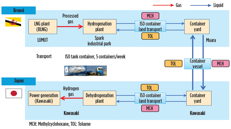
Fig. 7. Logistics flow for the AHEAD H2 supply chain demonstration project.
The planned capacity of the demo system is 210 metric tpy (210,000 kgy), which is approximately the amount required for a single fueling of around 40,000 FCEVs. In the case of the demo project, the H2 is burned in a power-generating gas turbine located within an existing site in Kawasaki, Japan. The two SPERA production sites—the hydrogenation site in Brunei (FIG. 8) and the dehydrogenation site in Kawasaki (FIG. 9)—have operated continuously throughout 2020, basically fulfilling all of the original goals of the demo program.
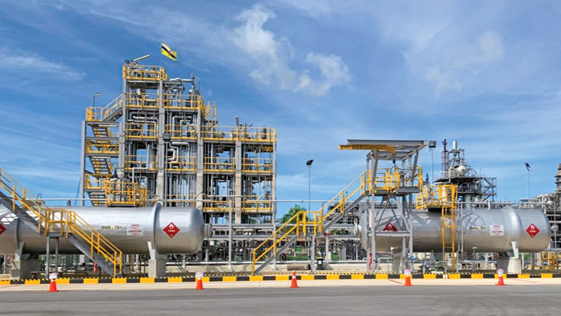
Fig. 8. Demonstration hydrogenation plant in Brunei.
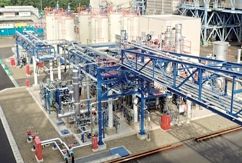
Fig. 9. Demonstration dehydrogenation plant in Kawasaki, Japan.
Power-to-gas demo. In parallel to demonstrating SPERA as part of a global supply chain, additional programs were undertaken to further demonstrate the robustness of the technology. A small-scale power-to-gas demo project outline is depicted in FIG. 10. This project was carried out in Yokohama, Japan and also funded by NEDO.
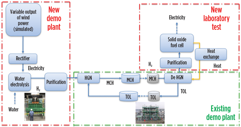
Fig. 10. Small-scale power-to-gas demonstration project in Yokohama, Japan.
Energy from a simulated wind farm was used to power an alkaline electrolyzer for H2 production. The recovered alkaline H2 was then purified and sent to the existing SPERA demo plant, as shown in FIG. 10. These steps demonstrate the ability to harness wind energy, which is then stored as H2 and can be transported to any site desired. In the demo project, the recovered H2 was purified and then utilized in a lab-scale solid oxide fuel cell (SOFC) for power production. In a real-world utilization scenario, for example, offshore wind energy could be harnessed and converted to transportable H2 that could then be transported by LOHC for use in clean power generation at another desired location. In this case, it is further demonstrated that having dehydrogenation adjacent to the SOFC makes possible efficient heat integration between the fuel cell, which generates waste heat, and the endothermic dehydrogenation plant.
Hydrogen fueling stations. An additional demo project funded by NEDO targeted the use of LOHC to transport H2 for use in distributed fueling stations. These stations could service passenger FCEVs or even larger fuel cells used in heavy-duty trucks or other large transport vehicles. For this study, a small-scale, packaged dehydrogenation facility was developed for testing (FIG. 11). In the process flow, methylcyclohexane from storage is dehydrogenated in the compact recovery plant, and then recovered H2 is purified to meet fuel cell specifications before being compressed to approximately 700 bar prior to use.
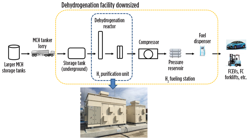
Fig. 11. Small-scale dehydrogenation facility developed for H2 fueling demonstration project.
The SPERA technology, having been proven at both the pilot and demo scale, was deemed ready for commercial roll-out. In the Kawasaki demonstration, H2 produced remotely was transported via LOHC over 5,000 km and ultimately consumed in a gas turbine used for generating electric power. The demo plant’s capacity of 210 metric tpy was simply a capacity of convenience—i.e., large enough to prove the capabilities of the supply chain while limiting the initial investment. Much larger and more ambitious transport programs have already been evaluated; these vary in size according to the specifics of the various applications.
The next step, envisioned for the 2025–2026 time frame, provides for utilization in mobility and industrial applications, along with gas turbine consumption of clean-burning H2 of up to 30% in the fuel. Plans for this second chain provide for up to 1 BNm3/yr of H2 (90,000 metric t).
By 2030, up to 3.3 BNm3/yr of H2 utilization is planned. This volume is equivalent to 300,000 metric tpy, according to Japan’s Hydrogen Strategy outlined in 2017. In addition, Japan announced a target to introduce 3 metric MMtpy of H2 use by 2030, as per the Ministry of Economy, Trade and Industry’s “Green growth strategy towards 2050 carbon neutrality,” released in December 2020. Significant H2 acceleration and volume increase is expected to meet this target (FIG. 12).
Fig. 12. Pathway to commercialization for the SPERA Hydrogen technology
Future applications consider greatly expanded mobility uses both in the form of private and public transport, accelerated use in materials and goods movement both at ports and in long-haul overland transport, clean industrial consumption, and gas turbine fuel with up to 100% H2.
Production of H2 via conventional methodologies, recovery of byproduct or through greener approaches, such as water electrolysis, have a marked effect on both the cost and availability of H2. When considering H2 as an alternative fuel, it is normal that the first question asked is usually “What is the delivered cost of H2?” How to best produce H2 for the future is a broad topic not covered by this article. The authors’ focus is to explore how to best deliver produced H2 reliably and at a competitive cost.
Concurrent to the demonstration of SPERA LOHC technology, a number of wide-ranging studies have been undertaken to explore competitive options for transportation. Both locally focused and long-haul transport have been considered and reviewed. Truck transport, rail, inland waterway barges, pipelines and ocean-going tankers have been compared in a number of studies (FIG. 13).
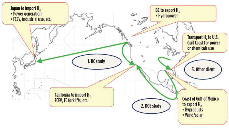
Fig. 13. Studies undertaken to explore competitive options for H2 transportation.
In 2019, a detailed study was concluded with the government of British Columbia in Canada that considered the efficient transport of H2 produced from low-cost hydropower. SPERA technology served as the basis, and transport of H2 from a coastal location was considered for delivery to Japan, to the city of Vancouver, Canada and to the port of Los Angeles in California, U.S.
Another study was completed in 2019 with a U.S.-based industrial partner to produce H2 from excess nuclear power in the Midwestern U.S. The LOHC was then transported to an industrial port located on the U.S. Gulf Coast for eventual dehydrogenation and subsequent distribution for both industrial use and/or clean power production. In this case, rail and barge transport options were investigated.
Lastly, a research laboratory of the U.S. DOE was engaged to complete another detailed transportation study. In this study, the recovery of H2 from existing U.S. Gulf Coast sources (cracker byproduct and chlor-alkali offgas) was compared with green production of H2 using both solar and wind energy, for transport to California for use as mobility fuel and power. Various transport options were considered, including rail and ocean-going, long-range chemical carriers.
With reference to the DOE study, several findings were noted:
SPERA has strength in large-scale transportation by ocean-going, long-range chemical carriers, as well as the potential to provide for H2 in many applications beyond the obvious uses in mobility, material movement and clean power generation (FIG. 14). H2 production by green or traditional methods can be utilized in remote locations for convenience and competitiveness, with shipment to any other location for centralized or decentralized recovery of H2, depending on the desirable end use at hand.
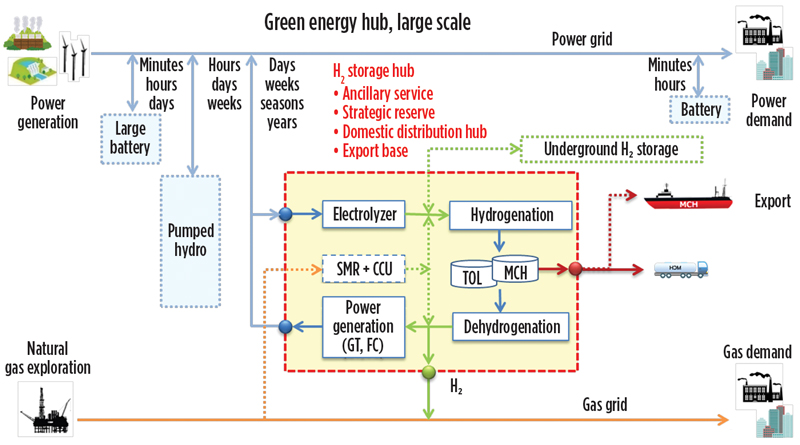
Fig. 14. SPERA technology as applied to a green energy hub.
Large-scale H2 storage is one method to consider for storage of fluctuating renewable power, such as seasonal fluctuation, at the point when renewable power is widely introduced in the power grid network. The H2 also can be used in the gas grid network.
The future for H2, both in the U.S. and internationally, is more a matter of “when” than “if.” Production and transportation costs for H2 will come down as usage ramps up based on increasing demand. The authors believe that it is better to familiarize users with H2 sooner rather than later, in anticipation of the transition from blue to green or renewable H2, as consumption rises. For now, the focus must be on adaptation.
The U.S. DOE study results show the possibility of meeting the prescribed DOE target of $3.10/kg of H2 (which dates back to 2015) in a large-scale H2 supply chain by utilizing recovered offgas H2 and SPERA transport from point of production to point of use. Blue H2 can be made from conventional steam reforming of natural gas for under $0.50/kg (variable production cost), assuming gas at $2.50/MMBtu.
H2 consumption in fuel cells for residential power, commercial applications, materials movement, personal mobility, mass transit and power generation will increase rapidly over the course of the next 10 yr. Challenges notwithstanding, these will be exciting times for both early adopters and infrastructure providers as we accelerate into a clean new world. H2T
NOTE
a The SPERA Hydrogen™ system is a trademark of Chiyoda Corp. SPERA is Latin for “hope.”
ROBERT V. SCHNEIDER, III is Senior Advisor to Chiyoda International Corp. in Houston, Texas. He was previously Senior Vice President and Director of Engineering and Licensing for Scientific Design Co. Inc. He has more than 40 yr of chemical process industry experience and a background in various process technologies including methanol, ammonia and ethylene oxide, industrial catalysis, sales and marketing, technology licensing and senior company management. Mr. Schneider previously held positions with Kvaerner Process (DAVY), the M.W Kellogg Co., United Catalysts/Sud-Chemie (now Clariant) and DuPont. He holds a BS degree in chemical engineering from the University of Louisville, Kentucky and an MBA degree from the University of South Florida. Mr. Schneider is a registered Professional Engineer in Texas, Florida and Kentucky.
DAISUKE KUROSAKI is the Group Leader for Hydrogen Supply Chain Development for Chiyoda Corp. in Yokohama, Japan. He has worked in a business development role in the H2 supply chain business since 2014; his assignment has included promotion of Chiyoda H2 transport technology business (SPERA), as well as responsibilities for the world’s first global H2 supply chain demonstration project between Brunei and Japan. Prior to joining the H2 business team, he led energy conservation studies for petrochemical complexes in Southeast Asia and the Middle East. He was involved in fuel cell cogeneration system development and wind farm project development before joining Chiyoda, and has 20 yr of experience in both technical and business development roles in H2 and related energy fields. Mr. Kurosaki holds BS and MS degrees in civil engineering from the University of Tokyo in Japan. As a part of his graduate studies, Mr. Kurosaki also studied at the University of California at Berkeley.
MASAAKI OKI is the Chief Coordinator for Hydrogen Supply Chain Development at Chiyoda Corp. in Yokohama, Japan. He has been in a business development role in the H2 supply chain business since 2019. His assignment has included promotion of Chiyoda H2 transport technology business (SPERA), as well as responsibilities for the world’s first global H2 supply chain demonstration project between Brunei and Japan. He was also the Lead Project Engineer for the Brunei hydrogenation plant. Prior to joining the H2 business team, Mr. Oki was Lead Process Engineer for an LNG receiving terminal project. Previous to that assignment, Mr. Oki supported Japan Methane Hydrate Operating Co. Ltd. in the development of methane hydrate technology. Mr. Oki holds BS and MS degrees in chemical engineering from the University of Kansai in Japan.