SPECIAL FOCUS: ADVANCES IN HYDROGEN TECHNOLOGY
G. W. HOWE and G. F. SKINNER, Gasconsult Ltd., London, UK; and A. J. FINN, Costain, Manchester, UK
Meeting net carbon-neutral targets by 2050 requires new clean energy sources. Hydrogen can be produced as a zero-carbon fuel and will be a major contributor to meeting this objective. The significance of H2 is illustrated by the formation of the Hydrogen Council in Q1 2017; the preparation of “The future of hydrogen” report by the IEA for the G20 meeting in Q2 2019; and the publication of “A hydrogen strategy for a climate-neutral Europe” by the European Commission in Q3 2020.
Zero-carbon H2 can be produced through electrolysis of water using renewable electric power (green H2); or through steam or autothermal reforming of natural gas, or gasification of coal (blue H2). Blue H2 production processes require carbon capture and storage to secure zero-carbon status.
Cost reductions will be needed for H2 to displace fossil fuels. While technology advances in electrolyzers and lower-cost renewable power will, over time, reduce the cost of green H2, the bulk of zero-carbon production will initially be blue H2, which, at present, can be produced at greater scale and lower cost.
Demand for H2 will be impacted by natural gas and carbon pricing. The latter provides governments the leverage to impact the rate and extent of H2’s displacement of fossil fuels and influence H2’s contribution to meeting the 2050 objectives.
Liquid H2 production. Producing liquid H2 (LH2) reduces volumes by 800 and reduces storage and distribution costs. Liquefaction will, therefore, be central to many H2-based schemes. All existing LH2 plants are small (typically < 15,000 metric tpy) and use a combination of liquid nitrogen evaporative precooling and Claude H2 expander cycle for final liquefaction. The requirement for liquid nitrogen means that larger LH2 plants require integration with, or close proximity to, an air separation unit. Aside from constrained supply logistics, use of liquid nitrogen is thermodynamically inefficient, resulting in a liquefaction power demand of 10 kWh/kg–15 kWh/kg LH2 on existing plants, equivalent to 30%–45% of the energy content of the H2 feed. This level of power demand is unsustainable at the higher plant capacities required to produce bulk LH2.
This article describes a low equipment count precooling concept integrated with an H2 expander cycle for final cooling and liquefaction. The dual-expander precooling configuration uses natural gas, a single, low-cost refrigerant, and avoids the infrastructure needed to transfer, store and blend conventional liquid refrigerants. For final cooling and liquefaction, the cycle uses the H2 feed as refrigerant and avoids external, high-cost refrigerants such as neon and helium.
Overall, the scheme achieves a favorable balance between capital and operating costs by combining simplicity, less equipment and low capital cost with a competitive power demand.a
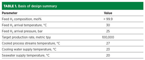
Basis of design. To provide a reference point for the data presented in this article, the basis of design is provided in TABLE 1. The basic premise is that the H2 feed derives from either a hydrocarbon-based production plant, such as a steam reformer (blue H2) or from electrolyzers (green H2).
In addressing the plant production capacity and the desire to meet 2050 carbon targets, the authors have reflected the need to make a significant impact on consumption of liquid transportation and industrial fuels, which are presently used at an approximate rate of 4,000 metric MMtpy. To provide perspective, the Hydrogen Council1 projects H2 consumption for transportation and industrial fuel of 38 exajoules per year in 2050 (1,050 metric MMtpy of oil equivalent). This would require an additional installed H2 plant capacity of approximately 400 metric MMtpy. If only 10% of the H2 was required as LH2, then this would require approximately 400 liquefaction plants, each with a capacity of 100,000 metric tpy.
Based on these challenging capacity parameters, the design capacity was selected as 100,000 metric tpy, which approximates the availability of maximum-sized electric-motor-driven H2 compression equipment.
The specified H2 arrival pressure of 25 bar is typical of the pressure of H2 supply from steam reforming H2 plants and existing PEM electrolyzers. This pressure affects the overall power requirement of the LH2 plant.
It has been assumed that seawater at 20°C will cool a closed circuit of treated water cooling the process coolers and heat exchangers within the LH2 plant.
Methane precooling H2 liquefaction. A schematic of the overall liquefaction process is shown in FIG. 1. The illustrated concept integrates a dual-expander methane precooling process with a cold-end H2 expander design. The precooling, however, could be combined with other cold-end arrangements using, for example, helium and/or neon refrigerants.
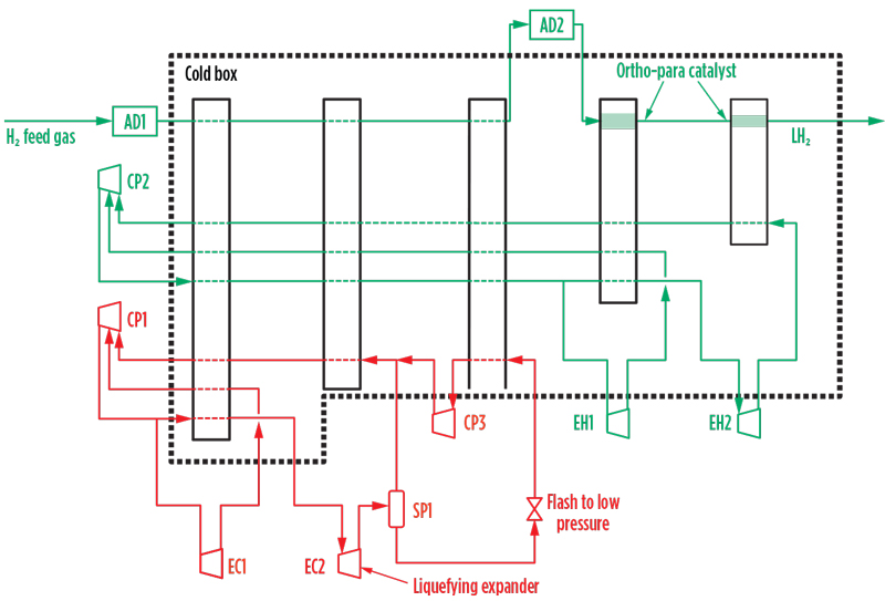
Fig. 1. Overall process configuration for methane precooling H2 liquefaction.
The precooling circuit, shown in red, was originally developed and patented for LNG application. The cold-end H2 cycle is shown in green.
Methane expander cycle. The methane make-up gas to the precooling system is assumed to be pipeline-quality natural gas. Given the limited volume of the initial fill and make-up quantities, molecular sieve pretreatment provides a practical solution to remove carbon dioxide (CO2), water vapor and residual hydrocarbons that would freeze in the liquefaction system. LH2 plants proximate to LNG liquefaction or regasification facilities and with access to pretreated LNG feed gas or regasified LNG may not require pretreatment facilities.
The methane cycle operates as a closed circuit with the methane refrigerant compressed and circulated by the electrically driven recycle compressor, CP1. The compressed gas then flows to the cold box comprising multi-passage brazed aluminum heat exchangers, which cool the H2 feed and the circulating H2 refrigerant streams to approximately –160°C. After preliminary chilling in the cold box, the compressed methane flows to the expander wheels of the two expander-compressors, EC1/EC2. The high-temperature expander, EC1, typically discharges at 25 bar/–50°C, and the low-temperature expander, EC2, discharges at 10 bar/–125°C. The cold outlet streams from EC1/EC2 return to the cold box, where they cool the H2 feed and the circulating refrigerant streams to approximately –120°C. EC1/EC2 are loaded by compressor wheels in series with the main recycle compressor, as illustrated in FIG. 2; they compress the circulating methane to 70 bar–100 bar at the inlet to the cold box.
The low-temperature expander, EC2, operates in partially liquefying mode and efficiently converts latent heat into mechanical work, improving cycle efficiency. This partial liquefaction (FIG. 2), which uses well-proven expander technology, reduces the total power demand of the H2 liquefaction process and is a distinctive feature.
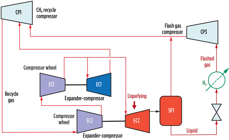
Fig. 2. Methane cycle power recovery and liquefying expander configuration.
The condensed liquid formed in EC2 is separated from the gas phase in separator SP1 and is then flashed to near-atmospheric pressure. The resulting two-phase methane stream is evaporated and reheated by further heat exchange with the H2 feed and the circulating H2 refrigerant streams, which are thereby cooled to –155°C. The evaporated and reheated flashed gas stream is recaptured to the system by the flash gas compressor, CP3, and routed together with the outlet gas stream from SP1 to CP1 suction for recompression and return to the expanders for further cooling duty.
The typical impact on precooling power demand of increasing liquids content at the outlet of EC2 is shown in FIG. 3. Power consumption is reduced as the liquid content of the expander outlet increases.
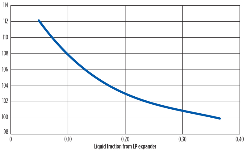
Fig. 3. Relative power vs. liquid fraction from low-pressure expander.
H2 cooling and liquefaction. The H2 cooling, liquefaction and refrigerant flows are shown schematically in FIG. 1. The two separate systems include the H2 feed stream and the H2 expander refrigeration cycle.
Feed gas H2 is pretreated in molecular sieve adsorbers (AD1) to remove impurities, such as traces of CO2 and water vapor, and fed to the cold box inlet. After precooling by the methane expander cycle to –150°C, the H2 feed is routed to parallel, second-stage, regenerable cryogenic adsorbers (AD2) to remove residual trace impurities, mainly nitrogen and hydrocarbons. The adsorbers accomplish several key functions:2
Multiple stages of ortho-H2 to para-H2 catalyst are provided, integrated with the cold end of the brazed aluminium exchanger system. Near-complete conversion of the ortho-H2 to the para-allotrope is essential prior to LH2 storage, as residual ortho-H2 to para-H2 conversion in storage is exothermic, causing significant boil-off losses.
After ortho-H2 to para-H2 conversion and further expansion, the H2 feed leaves the cold box as liquid H2 at 2 bar/–250°C. It is depressurized, if required, and routed to storage.
The H2 refrigerant system comprises a separate closed-cooling circuit with multiple expander stages that provide low-temperature refrigeration for liquefaction of the feed H2. The H2 in this second H2 system consists essentially of unequilibrated “normal H2” (75% ortho-H2 plus 25% para-H2).
The H2 recycle compressor (CP2) delivers precooled H2 to the expanders at 50 bar, with the first expander (EH1) typically discharging at 4.5 bar/–216°C and the last expander (EH2) discharging at 2.7 bar/–249°C. The expander outlet streams provide counter-current cooling of the H2 feed gas and are then routed to the CP2 suction and returned to EH1/EH2 for further cooling duty. EH1/EH2 recover power, which is used to reduce the overall power demand of the system.
The H2 expanders are both expected to require more than one impeller in series due to enthalpy drop limitations.
Design issues. In developing the overall system design, the authors have noted the difficulty in reconciling the available data on the properties of ortho-H2. This has been addressed by modifying the reference state of ortho-H2 in the National Institute of Standards and Technology’s REFerence fluid PROPerties (REFPROP) database.3
Alternative configurations. A number of variants to the described system have been investigated, as described in the following sections.
Nitrogen precooling refrigerant. The use of nitrogen (or a nitrogen/methane mixture) in place of methane in the precooling system has been investigated. With nitrogen, a lower precooled temperature of approximately –190°C may be attained, but the overall specific power of the liquefaction process was found to be up to 10% higher than with methane. However, due to the lower attainable final temperature of the precooling stage (around –190°C), there is a reduction in the power requirement of around 20% for the relatively expensive H2 compressor CP2, which may be significant in terms of capital cost.
Low-temperature H2 recycle compression. FIG. 4 shows a variant of the H2 liquefaction cycle that operates the H2 recycle compressor with a significantly sub-ambient suction temperature. The recycled H2 enters the first part of compressor CP2 typically at a temperature of –120°C. Alternatively, the inlet stream to compressor CP2 may be taken directly from the outlet stream of the H2 liquefier unit at a lower temperature.
Depending on the inlet temperature of compressor CP2, its power consumption may be reduced by approximately 50%, relative to the configuration with a near-ambient inlet temperature, as shown in FIG. 1. While this leads to an approximately equivalent increase in the power demand for the precooling methane compression, operation of the H2 compressor with a sub-ambient inlet temperature has advantages for H2 liquefaction:
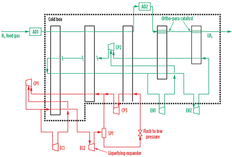
Fig. 4. Low-temperature H2 compression.
Process performance. A realistic expected specific power of the H2 liquefaction process is in the range of 6.7 kWh/kg–7.5 kWh/kg LH2, depending significantly on the LH2 delivery pressure and the efficiencies of the compressors and expanders. Other factors affecting the specific power include the disposition of the ortho-para conversion catalyst (in the heat exchangers, or external) and the selected precooling refrigerant (methane, nitrogen or combinations of these).
Relative process performance and configuration issues. Recognizing the inadequacies of present LH2 technology for the scale required to support the H2 economy, various configurations have been investigated by a number of parties. The IDEALHY consortium published data4 on a survey of various configurations of existing operating LH2 facilities and new concepts. An extract from the consortium’s data is provided in TABLE 2, which shows a drive to improvement in both the precooling and liquefaction circuits. A measure of caution is required in interpreting this data, as the bases of design for the various processes are not identical and predicted machine efficiencies vary significantly.
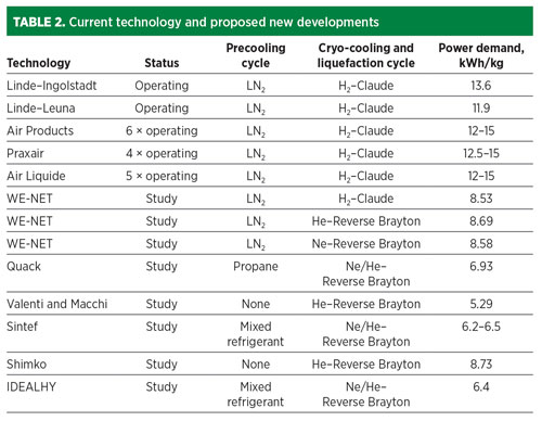
In terms of power demand, the most promising schemes indicate a move towards single mixed-refrigerant (SMR) precooling and use of efficient, though expensive refrigerants, neon and helium, for the liquefaction stage. Other work5 indicates that SMR precooling combined with a high-pressure Claude H2 cycle achieves power demand in the range of 6 kWh/kg–7 kWh/kg.
The authors sought to improve on these configurations with the following objectives:
The described scheme achieves these objectives:
Cost estimate. A cost estimate was developed for the inside battery limit liquefaction plant. The inputs to this estimate were a sized equipment list and supplier pricing data. The equipment list is provided in TABLE 3.
The cost estimate for the 100,000-tpy production unit is US$380 MM, based on a Q1 2021 instant execution basis. The following methodology was applied to develop the cost estimate:
° Owner’s costs
° Costs for fees and permits
° Finance costs
° Insurance costs
° Customs and import duties
° Taxes
° Forward escalation
° Liquid H2 storage costs
° Offsites and utilities costs.
Takeaway. H2 liquefaction by methane and nitrogen precooling processes incorporating a partially liquefying expander holds considerable promise as a low-cost, high-efficiency system. Significant engineering work, relevant to H2 application, was carried out as part of the scheme’s earlier development for LNG application.
Early-stage use of H2 as an energy vector, prior to its more widespread deployment, may require plants of a capacity below the 100,000-metric-tpy capacity selected as the basis of design. The application of the described process, given its simplicity and particular balance between operating and capital cost, may be enhanced at these lower plant capacity levels.
A patent for the described precooling process has been applied for covering methane and nitrogen refrigerants and mixtures of the two. A patent application has also been made for the use of the low-suction-temperature H2 recycle compression system.
LITERATURE CITED
1 Hydrogen Council, “Hydrogen scaling up: A sustainable pathway for the global energy transition,” November 2017, online: https://hydrogencouncil.com/wp-content/uploads/2017/11/Hydrogen-scaling-up-Hydrogen-Council.pdf
2 Cardella, U., “Large-scale hydrogen liquefaction under the aspect of economic viability,” Dissertation at the Technischen Universität München, May 17, 2018.
3 Leachman, J. W. et al., “International cryogenics monograph series—Thermodynamic properties of cryogenic fluids,” Ed. 2, Springer, New York, New York, 2017.
4 Essler, J. et al., “Report on technology overview and barriers to energy and cost efficient large scale hydrogen liquefaction,” Fuel Cells and Hydrogen Joint Undertaking, Grant Agreement No. 278177, June 5, 2012.
5 Cardella, U., “Large-scale liquid hydrogen production and supply,” Hydrogen Liquefaction
and Storage Symposium, Perth, Australia, September 26–27, 2019.
NOTE
a The methane expander precooling system (OHL—Optimized Hydrogen Liquefaction) described in this article is owned and licensed by Gasconsult Ltd. Data on equipment performance was provided by BHGE.
BILL HOWE is the CEO of Gasconsult Ltd. He graduated as a chemical engineer from Birmingham University and has spent 30 yr in the E&C industry, mainly with Foster Wheeler. He was Managing Director of Foster Wheeler’s South African affiliate and, subsequently, Director of Sales and Marketing at Foster Wheeler Reading in the UK.
GEOFF SKINNER is the Technical Director of Gasconsult Ltd. He graduated from Oxford University and joined Foster Wheeler UK in 1965. From 1981–1986, he was Technical Director of Foster Wheeler Synfuels Corp. in Livingston, New Jersey. Upon his return to the UK, he acted as a consultant to several multinational companies and has registered a number of patents, including LNG and OHL liquefaction processes.
ADRIAN FINN is Process Technology Manager at Costain, with responsibility for gas processing technology development and commercialization. He has nearly
40 yr of experience with Costain and has led approximately 100 feasibility studies, pre-FEED studies and FEED studies on international cryogenic gas processing projects with energy majors. He has authored more than 60 papers, holds 28 granted patents and has presented globally on cryogenic gas processing and process integration.